- 您現(xiàn)在的位置:買賣IC網(wǎng) > PDF目錄360441 > 74F632 32-Bit Parallel Error Detection and Correction Circuit PDF資料下載
參數(shù)資料
| 型號(hào): | 74F632 |
| 英文描述: | 32-Bit Parallel Error Detection and Correction Circuit |
| 中文描述: | 32位并行錯(cuò)誤檢測(cè)和校正電路 |
| 文件頁(yè)數(shù): | 4/14頁(yè) |
| 文件大?。?/td> | 225K |
| 代理商: | 74F632 |
第1頁(yè)第2頁(yè)第3頁(yè)當(dāng)前第4頁(yè)第5頁(yè)第6頁(yè)第7頁(yè)第8頁(yè)第9頁(yè)第10頁(yè)第11頁(yè)第12頁(yè)第13頁(yè)第14頁(yè)
Functional Description
(Continued)
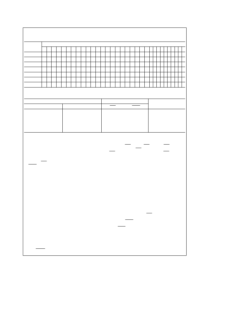
TABLE II. Parity Algorithm
Check Word
Bit
32-Bit Data Word
31 30 29 28 27 26 25 24 23 22 21 20 19 18 17 16 15 14 13 12 11 10 9 8 7 6 5 4 3 2 1 0
CB
0
X
X
X
X
X
X
X
X
X
X
X X X X
X
X
CB
1
X
X
X
X
X
X
X
X
X
X
X
X
X
X X X
CB
2
X
X
X
X
X
X
X
X
X
X
X
X
X
X X
X
CB
3
X
X
X
X
X
X
X
X
X
X
X
X X X
X X
CB
4
X
X
X
X
X
X
X
X
X
X
X X X X X X
CB
5
X
X
X
X
X
X
X
X
X
X
X
X
X
X
X X
CB
6
X
X
X
X
X
X
X
X
X X X X X X X X
The seven check bits are parity bits derived from the matrix of data bits as indicated by X for each bit.
TABLE III. Error Function
Total Number of Errors
Error Flags
Data Correction
32-Bit Data Word
7-Bit Check Word
ERR
MERR
0
1
0
1
2
0
0
0
1
1
0
2
H
L
L
L
L
L
H
H
H
L
L
L
Not Applicable
Correction
Correction
Interrupt
Interrupt
Interrupt
H
e
HIGH Voltage Level
L
e
LOW Voltage Level
If the parity of one or more of the check groups is incorrect,
an error has occurred and the proper error flag or flags will
be set LOW. Any single error in the 32-bit data word will
change the state of either three or five bits of the 7-bit
check word. Any single error in the 7-bit check word chang-
es the state of only that one bit. In either case, the single
error flag (ERR) will be set LOW while the dual error flag
(MERR) will remain HIGH.
Any 2-bit error will change the state of an even number of
check bits. The 2-bit error is not correctable since the parity
tree can only identify single-bit errors. Both error flags are
set LOW when any 2-bit error is detected.
Three or more simultaneous bit errors can cause the EDAC
to believe that no error, a correctable error, or an uncorrect-
able error has occurred and will produce erroneous results
in all three cases. It should be noted that the gross-error
conditions of all LOWs and all HIGHs will be detected.
As the corrected word is made available on the data I/O
port (DB
0
through DB
31
), the check word I/O port (CB
0
through CB
6
) presents a 7-bit syndrome error code. This
syndrome error code can be used to locate the bad memory
chip. See Table V for syndrome decoding.
READ-MODIFY-WRITE (BYTE CONTROL) OPERATIONS
The ’F632 device is capable of byte-write operations. The
39-bit word from memory must first be latched into the Data
Bit and Check Bit input latches. This is easily accomplished
by switching from the read and flag mode (S
1
e
H, S
0
e
L)
to the latch input mode (S
1
e
H, S
0
e
H). The EDAC will
then make any corrections, if necessary, to the data word
and place it at the input of the output data latch. This data
word must then be latched into the output data latch by
taking LEDBO from a LOW to a HIGH.
Byte control can now be employed on the data word
through the OEB
0
through OEB
3
controls. OEB
0
controls
DB
0
–DB
7
(byte 0), OEB
1
controls DB
8
–DB
15
(byte 1),
OEB
2
controls DB
16
–DB
23
(byte 2), and OEB
3
controls
DB
24
–DB
31
(byte 3). Placing a HIGH on the byte control will
disable the output and the user can modify the byte. If a
LOW is placed on the byte control, then the original byte is
allowed to pass onto the data bus unchanged. If the original
data word is altered through byte control, a new check word
must be generated before it is written back into memory.
This is easily accomplished by taking controls S
1
and S
0
LOW. Table VI lists the read-modify-write functions.
DIAGNOSTIC OPERATIONS
The ’F632 is capable of diagnostics that allow the user to
determine whether the EDAC or the memory is failing. The
diagnostic function tables will help the user to see the possi-
bilities for diagnostic control. In the diagnostic mode
(S
1
e
L, S
0
e
H), the check word is latched into the input
latch while the data input latch remains transparent. This
lets the user apply various data words against a fixed known
check word. If the user applies a diagnostic data word with
an error in any bit location, the ERR flag should be LOW. If a
diagnostic data word with two errors in any bit location is
applied, the MERR flag should be LOW. After the check
word is latched into the input latch, it can be verified by
taking OECB LOW. This outputs the latched check word.
The diagnostic data word can be latched into the output
data latch and verified. By changing from the diagnostic
mode (S
1
e
L, S
0
e
H) to the correction mode (S
1
e
H, S
0
e
H), the user can verify that the EDAC will correct the
diagnostic data word. Also, the syndrome bits can be pro-
duced to verify that the EDAC pinpoints the error location.
Table VII lists the diagnostic functions.
4
相關(guān)PDF資料 |
PDF描述 |
|---|---|
| 54F632 | 32-Bit Parallel Error Detection and Correction Circuit |
| 54F632DM | Error Detection & Correction (EDAC) |
| 54F632DMQB | Error Detection & Correction (EDAC) |
| 54F632DMQR | Error Detection & Correction (EDAC) |
| 54F632LM | Error Detection & Correction (EDAC) |
相關(guān)代理商/技術(shù)參數(shù) |
參數(shù)描述 |
|---|---|
| 74F632QC | 制造商:NSC 制造商全稱:National Semiconductor 功能描述:32-Bit Parallel Error Detection and Correction Circuit |
| 74F632VC | 制造商:NSC 制造商全稱:National Semiconductor 功能描述:32-Bit Parallel Error Detection and Correction Circuit |
| 74F64 | 制造商:NSC 制造商全稱:National Semiconductor 功能描述:4-2-3-2-Input AND-OR-Invert Gate |
| 74F64 WAF | 制造商:Fairchild Semiconductor Corporation 功能描述: |
| 74F640 | 制造商:FAIRCHILD 制造商全稱:Fairchild Semiconductor 功能描述:Octal Bus Transceiver with 3-STATE Outputs |
發(fā)布緊急采購(gòu),3分鐘左右您將得到回復(fù)。