- 您現(xiàn)在的位置:買賣IC網(wǎng) > PDF目錄372977 > ZN447D Converter IC PDF資料下載
參數(shù)資料
| 型號: | ZN447D |
| 英文描述: | Converter IC |
| 中文描述: | 轉(zhuǎn)換器IC |
| 文件頁數(shù): | 16/18頁 |
| 文件大小: | 289K |
| 代理商: | ZN447D |
ZN448/9
16
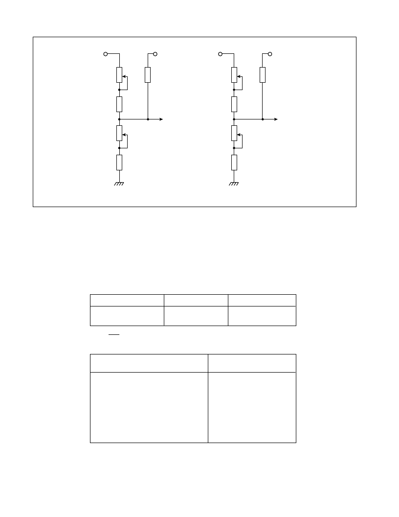
Fig.19 Bipolar operation component values
AIN
VREF
TO PIN 6
13k
7k5
5k
OFFSET
ADJUST
13k
5k
GAIN
ADJUST
± 2% RESISTORS
±20% POTENTIOMETERS
±5VOLTS FULL SCALE
AIN
VREF
TO PIN 6
27k
8k2
10k
OFFSET
ADJUST
8k2
5k
GAIN
ADJUST
±10VOLTS FULL SCALE
Bipolar adjustment prodedure
(i) Apply continuous SC pulses at intervals long enough to
allow a complete conversion and monitor the digital
outputs.
(ii) Apply -(FS -0.5LSB) to A
and adjust off-set until the bit 8
(LSB) output just flickers between 0 and 1 with all other bits
at 0.
(iii) Apply +(FS -1.5LSB) to A
and adjust gain until the 8 bit
just flickers between 0 and 1 with all other bits at 1.
(iv)Repeat step (ii).
Bipolar setting up points
+(FS -1.5LSB)
+4.9414V
+9.8828V
1LSB =2FS
256
Input range,
±
FS
+5V
+10V
-(FS -0.5LSB)
-4.9805V
-9.9609V
Bipolar logic coding
Analogue input (A
)
(Nominal code centre value)
+(FS - 1LSB)
+(FS - 2LSB)
+0.5FS
+1LSB
0
-1LSB
-0.5FS
-(FS - 1LSB)
-FS
Output code
(offset binary)
11111111
11111110
11000000
10000001
10000000
01111111
01000000
00000001
00000000
相關(guān)PDF資料 |
PDF描述 |
|---|---|
| ZN447E | Converter IC |
| ZN447J | Converter IC |
| ZN448D | Converter IC |
| ZN448J | Converter IC |
| ZN449J | Converter IC |
相關(guān)代理商/技術(shù)參數(shù) |
參數(shù)描述 |
|---|---|
| ZN447E | 制造商:未知廠家 制造商全稱:未知廠家 功能描述:Converter IC |
| ZN447J | 制造商:未知廠家 制造商全稱:未知廠家 功能描述:Converter IC |
| ZN448 | 制造商:未知廠家 制造商全稱:未知廠家 功能描述:8-BIT MICROPROCESSOR COMPATIBLE A-D CONVERTER |
| ZN448D | 制造商:未知廠家 制造商全稱:未知廠家 功能描述:Converter IC |
| ZN448E | 制造商:GPS 功能描述: |
發(fā)布緊急采購,3分鐘左右您將得到回復(fù)。