- 您現(xiàn)在的位置:買賣IC網(wǎng) > PDF目錄376461 > XRT73LC04AIV (EXAR CORP) 4 CHANNEL DS3/E3/STS-1 LINE INTERFACE UNIT PDF資料下載
參數(shù)資料
| 型號: | XRT73LC04AIV |
| 廠商: | EXAR CORP |
| 元件分類: | 數(shù)字傳輸電路 |
| 英文描述: | 4 CHANNEL DS3/E3/STS-1 LINE INTERFACE UNIT |
| 中文描述: | DATACOM, PCM TRANSCEIVER, PQFP144 |
| 封裝: | 20 X 20 MM, 1.40 MM HEIGHT, TQFP-144 |
| 文件頁數(shù): | 51/64頁 |
| 文件大小: | 360K |
| 代理商: | XRT73LC04AIV |
第1頁第2頁第3頁第4頁第5頁第6頁第7頁第8頁第9頁第10頁第11頁第12頁第13頁第14頁第15頁第16頁第17頁第18頁第19頁第20頁第21頁第22頁第23頁第24頁第25頁第26頁第27頁第28頁第29頁第30頁第31頁第32頁第33頁第34頁第35頁第36頁第37頁第38頁第39頁第40頁第41頁第42頁第43頁第44頁第45頁第46頁第47頁第48頁第49頁第50頁當(dāng)前第51頁第52頁第53頁第54頁第55頁第56頁第57頁第58頁第59頁第60頁第61頁第62頁第63頁第64頁

XRT73LC04A
4 CHANNEL DS3/E3/STS-1 LINE INTERFACE UNIT
REV. 1.0.1
47
4.0
DIAGNOSTIC FEATURES OF THE
XRT73LC04A
The XRT73LC04A supports equipment diagnostic ac-
tivities by supporting the following Loop-Back modes
within each channel.
Analog Local Loop-Back.
Digital Local Loop-Back
Remote Loop-Back
N
OTE
:
In this data sheet we use the convention that Chan-
nel(n) refers to either channel 0, 1, 2 or 3. Similarly, specific
input and output pins uses this convention to denote which
channel it is associated with.
4.1
T
HE
A
NALOG
L
OCAL
L
OOP
-B
ACK
M
ODE
When a given channel is configured to operate in the
Analog Local Loop-Back Mode, the channel ignores
any signals that are input to its RTIP_(n) and
RRing_(n) input pins. The Transmitting Terminal
Equipment transmits clock and data into this channel
via the TPData_(n), TNData_(n) and TxClk_(n) input
pins. This data is processed through the Transmit
Clock Duty Cycle Adjust PLL and the HDB3/B3ZS
Encoder. Finally, this data is output to the line via the
TTIP_(n) and TRing_(n) output pins. Additionally, this
data which is being output via the TTIP_(n) and
TRing_(n) output pins is also looped back into the At-
tenuator/Receive Equalizer Block. Consequently, this
data is processed through the entire Receive Section
of the channel. After this post-Loop-Back data has
been processed through the Receive Section it out-
puts to the Near-End Receiving Terminal Equipment
via the RPOS_(n), RNEG_(n) and RxClk_(n) output
pins.
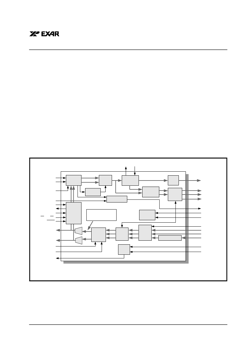
Figure 33 illustrates the path that the data takes when
the channel is configured to operate in the Analog Lo-
cal Loop-Back Mode.
Configure a given channel to operate in the Analog
Local Loop-Back Mode by employing either one of
the following two steps
a. Operating in the HOST Mode
N
OTE
:
See Table 2 for a description of Command Regis-
ters and Addresses for the different channels.
To configure Channel (n) to operate in the Analog Lo-
cal Loop-Back Mode, write a “1" into the LLB_(n) bit-
field and a "0" into the RLB_(n) bit-field within Com-
mand Register CR4.
F
IGURE
33. A
CHANNEL
OPERATING
IN
THE
A
NALOG
L
OCAL
L
OOP
-B
ACK
M
ODE
AGC/
Equalizer
Peak
Detector
LOS Detector
Slicer
Clock
Recovery
Data
Recovery
Invert
Loop MUX
HDB3/
B3ZS
Decoder
LOSTHR_(n)
SDI
SDO
SClk
CS/(SR/DR)
REGR
RTIP_(n)
RRing_(n)
REQEN_(n)
RxClk_(n)
RPOS_(n)
RNEG_(n)
LCV_(n)
RLOS_(n)
LLB_(n)
RLB_(n)
TAOS_(n)
TPData_(n)
TNData_(n)
TxClk_(n)
Notes: 1. (n) = 0, 1, 2, or 3 for respective Channels
2. Serial Processor Interface input pins are shared by the four Channels in HOST Mode and redefined in
Hardware Mode.
RLOL_(n) EXClk_(n)
Device
Monitor
MTIP_(n)
MRing_(n)
Transmit
Logic
Duty Cycle Adjust
TxLEV_(n)
TxOFF_(n)
DMO_(n)
TTIP_(n)
TRing_(n)
Pulse
Shaping
HDB3/
B3ZS
Encoder
Serial
Processor
Interface
Analog Local
Loop-Back Path
相關(guān)PDF資料 |
PDF描述 |
|---|---|
| XRT73R06 | SIX CHANNEL E3/DS3/STS-1 LINE INTERFACE UNIT |
| XRT73R06IB | SIX CHANNEL E3/DS3/STS-1 LINE INTERFACE UNIT |
| XRT73R12 | TWELVE CHANNEL E3/DS3/STS-1 LINE INTERFACE UNIT |
| XRT73R12IB | TWELVE CHANNEL E3/DS3/STS-1 LINE INTERFACE UNIT |
| XRT74L73 | 3 CHANNEL, ATM UNI/PPP DS3/E3 FRAMING CONTROLLER |
相關(guān)代理商/技術(shù)參數(shù) |
參數(shù)描述 |
|---|---|
| XRT73LC04AIV-F | 功能描述:外圍驅(qū)動器與原件 - PCI 4-Ch DS3, E3, STS-1 RoHS:否 制造商:PLX Technology 工作電源電壓: 最大工作溫度: 安裝風(fēng)格:SMD/SMT 封裝 / 箱體:FCBGA-1156 封裝:Tray |
| XRT73R06 | 制造商:EXAR 制造商全稱:EXAR 功能描述:SIX CHANNEL E3/DS3/STS-1 LINE INTERFACE UNIT |
| XRT73R06ES | 功能描述:網(wǎng)絡(luò)控制器與處理器 IC RoHS:否 制造商:Micrel 產(chǎn)品:Controller Area Network (CAN) 收發(fā)器數(shù)量: 數(shù)據(jù)速率: 電源電流(最大值):595 mA 最大工作溫度:+ 85 C 安裝風(fēng)格:SMD/SMT 封裝 / 箱體:PBGA-400 封裝:Tray |
| XRT73R06IB | 功能描述:外圍驅(qū)動器與原件 - PCI RoHS:否 制造商:PLX Technology 工作電源電壓: 最大工作溫度: 安裝風(fēng)格:SMD/SMT 封裝 / 箱體:FCBGA-1156 封裝:Tray |
| XRT73R06IB-F | 功能描述:外圍驅(qū)動器與原件 - PCI RoHS:否 制造商:PLX Technology 工作電源電壓: 最大工作溫度: 安裝風(fēng)格:SMD/SMT 封裝 / 箱體:FCBGA-1156 封裝:Tray |
發(fā)布緊急采購,3分鐘左右您將得到回復(fù)。