- 您現(xiàn)在的位置:買賣IC網(wǎng) > PDF目錄203632 > W78M64110SBI (MICROSEMI CORP-PMG MICROELECTRONICS) 8M X 64 FLASH 3.3V PROM, 110 ns, PBGA159 PDF資料下載
參數(shù)資料
| 型號: | W78M64110SBI |
| 廠商: | MICROSEMI CORP-PMG MICROELECTRONICS |
| 元件分類: | PROM |
| 英文描述: | 8M X 64 FLASH 3.3V PROM, 110 ns, PBGA159 |
| 封裝: | 13 X 22 MM, 1.27 MM PITCH, PLASTIC, BGA-159 |
| 文件頁數(shù): | 16/50頁 |
| 文件大小: | 1679K |
| 代理商: | W78M64110SBI |
第1頁第2頁第3頁第4頁第5頁第6頁第7頁第8頁第9頁第10頁第11頁第12頁第13頁第14頁第15頁當(dāng)前第16頁第17頁第18頁第19頁第20頁第21頁第22頁第23頁第24頁第25頁第26頁第27頁第28頁第29頁第30頁第31頁第32頁第33頁第34頁第35頁第36頁第37頁第38頁第39頁第40頁第41頁第42頁第43頁第44頁第45頁第46頁第47頁第48頁第49頁第50頁
23
White Electronic Designs Corporation (602) 437-1520 www.whiteedc.com
White Electronic Designs
W78M64VP-XSBX
November 2009
2010 White Electronic Designs Corp. All rights reserved
Rev. 10
White Electronic Designs Corp. reserves the right to change products or specications without notice.
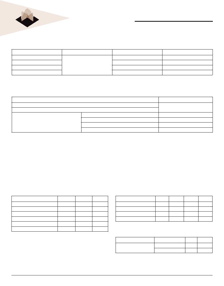
TABLE 25 SECURED SILICON SECTOR EXIT
(LLD Function = lld_SecSiSectorExitCmd)
Cycle
Operation
Word Address
Data
Unlock Cycle 1
Write
Base + 555h
00AAh
Unlock Cycle 2
Base + 2AAh
0055h
Exit Cycle 3
Base + 555h
0088h
Exit Cycle 4
Base + 000h
0000h
Note:
Base = Base Address.
TABLE 26 ABSOLUTE MAXIMUM RATINGS
Description
Rating
Storage Temperature
-55C to +125C
Ambient Temperature with Power Applied
Voltage with Respect to Ground
All Inputs and I/Os except as noted below (Note 1)
-0.5V to VCC + 0.5V
VCC (Note 1)
-0.5V to +4.0 V
VIO
-0.5V to +4.0 V
A9 and ACC (Note 2)
0.5V to +12.5V
Notes
1.
Minimum DC voltage on input or I/Os is –0.5 V. During voltage transitions, inputs or I/Os may undershoot VSS to –2.0 V for periods of up to 20 ns. See FIG: 11. Maximum DC voltage
on input or I/Os is VCC + 0.5 V. During voltage transitions inputs or I/Os may overshoot to VCC + 2.0 V for periods up to 20 ns. See FIG: 12.
2.
Minimum DC input voltage on pins A9 and ACC is -0.5V. During voltage transitions, A9 and ACC may overshoot VSS to –2.0 V for periods of up to 20 ns. See FIG: 11. Maximum DC
voltage on pins A9 and ACC is +12.5 V, which may overshoot to 14.0 V for periods up to 20 ns.
3.
No more than one output may be shorted to ground at a time. Duration of the short circuit should not be greater than one second.
4.
Stresses above those listed under “Absolute Maximum Ratings” may cause permanent damage to the device. This is a stress rating only; functional operation of the device at these
or any other conditions above those indicated in the operational sections of this data sheet is not implied. Exposure of the device to absolute maximum rating conditions for extended
periods may affect device reliability.
TABLE 28 RECOMMENDED OPERATING
CONDITIONS
Parameter
Symbol
Min
Max
Unit
Supply Voltage
VCC
3.0
3.6
V
I/O Supply Voltage
VIO
3.0
3.6
V
Operating Temp. (Mil.)
TA
-55
+125
°C
Operating Temp. (Ind.)
TA
-40
+85
°C
Note: For all AC and DC specications: VIO = VCC
TABLE 27 CAPACITANCE
TA = +25°C, f = 1.0MHz
Parameter
Symbol
Max
Unit
WE# capacitance
CWE
13
pF
CS# capacitance
CCS
25
pF
Data I/O capacitance
CI/O
15
pF
Address input capacitance
CAD
30
pF
RY/BY#
CRB
40
pF
OE# capacitance
COE
35
pF
This parameter is guaranteed by design but not tested.
TABLE 29 DATA RETENTION
Parameter
Test Conditions
Min
Unit
Pattern Data
Retention Time
150°C
10
Years
125°C
20
Years
相關(guān)PDF資料 |
PDF描述 |
|---|---|
| W78M64120SBI | 8M X 64 FLASH 3.3V PROM, 120 ns, PBGA159 |
| W78M64110SBC | 8M X 64 FLASH 3.3V PROM, 110 ns, PBGA159 |
| W78M64V100SBC | 8M X 64 FLASH 3.3V PROM MODULE, 100 ns, PBGA159 |
| W78M64VP120SBM | SPECIALTY MEMORY CIRCUIT, PBGA156 |
| W78M64VP120SBI | SPECIALTY MEMORY CIRCUIT, PBGA156 |
相關(guān)代理商/技術(shù)參數(shù) |
參數(shù)描述 |
|---|---|
| W78M64VP110SBM | 制造商:Microsemi Corporation 功能描述:8MX64 FLASH 3.3V PAGE MODE - Bulk |
| W78M64V-XSBX | 制造商:未知廠家 制造商全稱:未知廠家 功能描述:Flash MCP |
| W78NCSX-23 | 功能描述:低信號繼電器 - PCB 4PDT 3A 24VDC IND RoHS:否 制造商:NEC 觸點(diǎn)形式:2 Form C (DPDT-BM) 觸點(diǎn)電流額定值: 線圈電壓:5 V 最大開關(guān)電流:1 A 線圈電流:1 A 線圈類型:Non-Latching 功耗:140 mW 端接類型:SMT 絕緣: 介入損耗: |
| W78PCX-1 | 制造商:Magnecraft 功能描述: |
| W78PCX-2 | 制造商:Magnecraft 功能描述: |
發(fā)布緊急采購,3分鐘左右您將得到回復(fù)。