- 您現(xiàn)在的位置:買賣IC網(wǎng) > PDF目錄300050 > UHE-5/6000-D48TR-C (MURATA POWER SOLUTIONS INC) 1-OUTPUT 30 W DC-DC REG PWR SUPPLY MODULE PDF資料下載
參數(shù)資料
| 型號(hào): | UHE-5/6000-D48TR-C |
| 廠商: | MURATA POWER SOLUTIONS INC |
| 元件分類: | 電源模塊 |
| 英文描述: | 1-OUTPUT 30 W DC-DC REG PWR SUPPLY MODULE |
| 封裝: | ROHS COMPLIANT, PLASTIC PACKAGE-9 |
| 文件頁數(shù): | 5/16頁 |
| 文件大?。?/td> | 487K |
| 代理商: | UHE-5/6000-D48TR-C |
UHE Series
Isolated, High Efciency, 1.6" × 2"
2-10 Amp, 12-30 Watt DC/DC Converters
MDC_UHE_12-30W Series.B18 Page 13 of 16
www.murata-ps.com
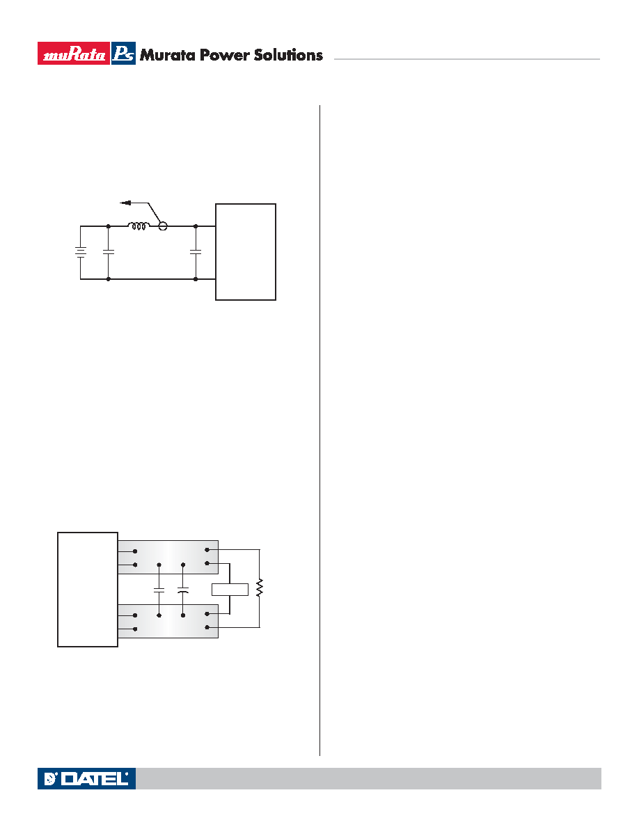
CIN
VIN
CBUS
LBUS
CIN = 33μF, ESR < 700m
@ 100kHz
CBUS = 220μF, ESR < 100m
@ 100kHz
LBUS = 12μH
+INPUT
–INPUT
CURRENT
PROBE
TO
OSCILLOSCOPE
+
–
C1
C1 = 0.47μF CERAMIC
C2 = NA
LOAD 2-3 INCHES (51-76mm) FROM MODULE
C2
RLOAD
COPPER STRIP
SCOPE
+OUTPUT
–OUTPUT
+SENSE
–SENSE
In critical applications, output ripple/noise (also referred to as periodic and
random deviations or PARD) may be reduced below specied limits using lter-
ing techniques, the simplest of which is the installation of additional external
output capacitors. These output caps function as true lter elements and
should be selected for bulk capacitance, low ESR and appropriate frequency
response. All external capacitors should have appropriate voltage ratings and
be located as close to the converter as possible. Temperature variations for all
relevant parameters should also be taken carefully into consideration.
The most effective combination of external I/O capacitors will be a function
of line voltage and source impedance, as well as particular load and layout
conditions. Our Applications Engineers can recommend potential solutions and
discuss the possibility of our modifying a given device's internal ltering to
meet your specic requirements. Contact our Applications Engineering Group
for additional details.
Floating Outputs
Since these are isolated DC/DC converters, their outputs are "oating" with
respect to their input. Designers will normally use the –Output (pin 7) as the
ground/return of the load circuit. You can, however, use the +Output (pin 6) as
ground/return to effectively reverse the output polarity.
Minimum Output Loading Requirements
UHE converters employ a synchronous-rectier design topology and all models
regulate within spec and are stable under no-load to full load conditions.
Operation under no-load conditions however might slightly increase the output
ripple and noise.
Thermal Shutdown
These UHE converters are equipped with thermal-shutdown circuitry. If envi-
ronmental conditions cause the internal temperature of the DC/DC converter to
rise above the designed operating temperature, a precision temperature sensor
will power down the unit. When the internal temperature decreases below the
threshold of the temperature sensor, the unit will self start. See Performance/
Functional Specications.
Output Overvoltage Protection
UHE output voltages are monitored for an overvoltage condition via magnetic
feedback. The signal is coupled to the primary side and if the output voltage
rises to a level which could be damaging to the load, the sensing circuitry will
power down the PWM controller causing the output voltages to decrease. Fol-
lowing a time-out period the PWM will restart, causing the output voltages to
ramp to their appropriate values. If the fault condition persists, and the output
voltages again climb to excessive levels, the overvoltage circuitry will initiate
another shutdown cycle. This on/off cycling is referred to as "hiccup" mode.
Contact MPS for an optional output overvoltage monitor circuit using a
comparator which is optically coupled to the primary side thus allowing tighter
and more precise control.
Current Limiting
As soon as the output current increases to 10% to 50% above its rated value,
the DC/DC converter will go into a current-limiting mode. In this condition, the
output voltage will decrease proportionately with increases in output current,
thereby maintaining somewhat constant power dissipation. This is commonly
referred to as power limiting. Current limit inception is dened as the point at
which the full-power output voltage falls below the specied tolerance. See
Performance/Functional Specications. If the load current, being drawn from
the converter, is signicant enough, the unit will go into a short circuit condition
as specied under “Performance.”
Short Circuit Condition
When a converter is in current-limit mode, the output voltage will drop as
the output current demand increases. If the output voltage drops too low, the
magnetically coupled voltage used to develop primary side voltages will also
drop, thereby shutting down the PWM controller. Following a time-out period,
the PWM will restart causing the output voltages to begin ramping to their
appropriate values. If the short-circuit condition persists, another shutdown
cycle will be initiated. This on/off cycling is referred to as “hiccup” mode. The
hiccup cycling reduces the average output current, thereby preventing internal
temperatures from rising to excessive levels. The UHE is capable of enduring
an indenite short circuit output condition.
in conductors from backplane to the DC/DC. Input caps should be selected
for bulk capacitance (at appropriate frequencies), low ESR, and high rms-
ripple-current ratings. The switching nature of DC/DC converters requires that
dc voltage sources have low ac impedance as highly inductive source imped-
ance can affect system stability. In Figure 2, CBUS and LBUS simulate a typical
dc voltage bus. Your specic system conguration may necessitate additional
considerations.
In Figure 3, the two copper strips simulate real-world pcb impedances
between the power supply and its load. In order to minimize measurement errors,
scope measurements should be made using BNC connectors, or the probe
ground should be less than inch and soldered directly to the xture.
Figure 2. Measuring Input Ripple Current
Figure 3. Measuring Output Ripple/Noise (PARD)
相關(guān)PDF資料 |
PDF描述 |
|---|---|
| UHE0J122 | 15V 200 mW SOD-923 Zener 5% Tolerance |
| UHE0J152 | 16V 200 mW SOD-923 Zener 2% Tolerance |
| UHE0J153 | 16V 200 mW SOD-923 Zener 5% Tolerance |
| UL62H1708AS1A55G1 | 128K X 8 STANDARD SRAM, 55 ns, PDSO32 |
| ULQ-1.5/25-D24PL2 | 1-OUTPUT DC-DC REG PWR SUPPLY MODULE |
相關(guān)代理商/技術(shù)參數(shù) |
參數(shù)描述 |
|---|---|
| UHE-ER14250-S | 功能描述:消費(fèi)電池與相機(jī)電池 3.6V 1.2AH STAINLESS STEEL RoHS:否 制造商:FDK Batteries 電池大小:CR1/3N 輸出電壓:3 V 容量:160 mAh 化學(xué)性質(zhì):Lithium 端接類型:Pressure Contacts 可再充電/不可再充電:Non-Rechargeable |
| UHE-ER14505-S | 功能描述:消費(fèi)電池與相機(jī)電池 3.6V 2.4AH STAINLESS STEEL RoHS:否 制造商:FDK Batteries 電池大小:CR1/3N 輸出電壓:3 V 容量:160 mAh 化學(xué)性質(zhì):Lithium 端接類型:Pressure Contacts 可再充電/不可再充電:Non-Rechargeable |
| UHF10JT | 制造商:VISHAY 制造商全稱:Vishay Siliconix 功能描述:High Voltage Ultrafast Rectifier |
| UHF10JT-E3/45 | 功能描述:整流器 600 Volt 10A 25ns RoHS:否 制造商:Vishay Semiconductors 產(chǎn)品:Standard Recovery Rectifiers 配置: 反向電壓:100 V 正向電壓下降: 恢復(fù)時(shí)間:1.2 us 正向連續(xù)電流:2 A 最大浪涌電流:35 A 反向電流 IR:5 uA 安裝風(fēng)格:SMD/SMT 封裝 / 箱體:DO-221AC 封裝:Reel |
| UHF10JT-E3/4W | 制造商:Vishay Semiconductors 功能描述:10A,600V,25NS,SINGLE FER PLANAR - Rail/Tube |
發(fā)布緊急采購,3分鐘左右您將得到回復(fù)。