- 您現(xiàn)在的位置:買賣IC網(wǎng) > PDF目錄225366 > U3900BM-AFN Programmable Telephone Audio Processor PDF資料下載
參數(shù)資料
| 型號: | U3900BM-AFN |
| 英文描述: | Programmable Telephone Audio Processor |
| 中文描述: | 程控電話音頻處理器 |
| 文件頁數(shù): | 17/34頁 |
| 文件大小: | 762K |
| 代理商: | U3900BM-AFN |
第1頁第2頁第3頁第4頁第5頁第6頁第7頁第8頁第9頁第10頁第11頁第12頁第13頁第14頁第15頁第16頁當前第17頁第18頁第19頁第20頁第21頁第22頁第23頁第24頁第25頁第26頁第27頁第28頁第29頁第30頁第31頁第32頁第33頁第34頁
U3900BM
Rev. A2, 25-Aug-98
Target Specification
24 (34)
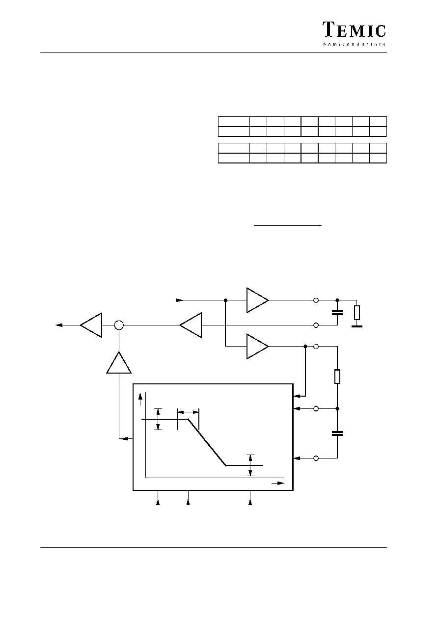
13 Sidetone System
The Sidetone Balancing (STB) has the task to reduce the
crosstalk from LTX (microphone) to LRX (earpiece) in
the frequency range of 0.3 to 3.4 kHz. The LTX signal is
converted into a current in the MOD block. This current
is transformed into a voltage signal (LINE) by the line
impedance ZL. The LINE signal is fed into the summing
amplifier DIFF1 via capacitor CK and attenuator AMP1.
On the other side the LTX buffered by STOAMP drives
an external low-pass filter (RST, CST). The external low-
pass filter and the internal STB have the transfer function
drawn in the STB box. The amplified STB-output signal
drives the negative input of the summing block. If both
signals at the DIFF1 block are equal in level and phase,
we have a good suppression of the LTX signal. In this
condition the frequency and phase response of the STB
block will represent the frequency curve on line.
In real live the line impedance ZL varies strongly for
different users. To reach a good suppression with one
application for all different line impendances, the STB
function is programmable.
The 3 programmable parameters are
1.
LF (gain at low frequency).
LF has 15 programming steps. LF(0) gives –2 dB
gain, LF(15) gives 5.5 dB gain.
LF
0
1
2
3
4
5
6
7
Step gain
–2
–1.3
–0.6
0.1
0.6
1.0
1.3
1.6
LF
8
9
10
11
12
13
14
15
Step gain
1.9
2.2
2.5
3.0
3.6
4.2
4.8
5.5
STO_DIFF(LF) = (–10 dB – 2 dB + 0.5 dB
LF + 9 dB)
LTX
2.
P (the pole position of the lowpass).
The P adjustment has 31 Steps. P(0) means the
lowpass determined by the external application
(RST, CST). The internally processed low-pass
frequency is fixed by this equation.
f(P)
+
1
2
p
CST
RST
1.122
P
3.
SL
(sidetone slope; the pole frequency of the highpass)
The SL have 3 steps. SL(0) is a lower frequency of the
highpass. SL(3) is a higher frequency of the highpass.
With SL we can influence the suppression at high
frequencies.
14579
–10dB
LF
f
P
SL
g
STC
STRC
0–7dB
STOAMP
STO
8.2 k
STO
CTO
33 nF
8dB
MOD
RECIN
LINE
–10dB
AMP1
9dB
STO_DIFF
DIFF1
AMP2
+
–
AGARX
LTX
LRX
CK
ZL
Sidetone balancing
LF
P
SL
Figure 26. Programmable sidetone supression circuit
相關PDF資料 |
PDF描述 |
|---|---|
| U3900BM-AFNG3 | Programmable Telephone Audio Processor |
| U4479B | DVB-Cable IF Converter and Full Multi-Standard Video-/Sound IF Processing |
| U4479B-MFLG3 | DVB-Cable IF Converter and Full Multi-Standard Video-/Sound IF Processing |
| U4488B | Quasi-Split Sound Circuit and AM Demodulator |
| U54-W-8 | GENERAL PURPOSE INDUCTOR |
相關代理商/技術參數(shù) |
參數(shù)描述 |
|---|---|
| U3900BM-AFNG3 | 制造商:TEMIC 制造商全稱:TEMIC Semiconductors 功能描述:Programmable Telephone Audio Processor |
| U392N | 制造商:APEM 功能描述:Switch Hardware |
| U39J1ZGE9 | 制造商:C&K Components 功能描述:- Bulk |
| U39MYW1QE | 制造商:C&K Components 功能描述:U39MYW1QE - Bulk |
| U3B | 制造商:VISHAY 制造商全稱:Vishay Siliconix 功能描述:Surface Mount Ultrafast Plastic Rectifier |
發(fā)布緊急采購,3分鐘左右您將得到回復。