- 您現(xiàn)在的位置:買賣IC網(wǎng) > PDF目錄272835 > TXS120ZA-R3H (POWER-ONE INC) 1-OUTPUT 180 W DC-DC REG PWR SUPPLY MODULE PDF資料下載
參數(shù)資料
| 型號(hào): | TXS120ZA-R3H |
| 廠商: | POWER-ONE INC |
| 元件分類: | 電源模塊 |
| 英文描述: | 1-OUTPUT 180 W DC-DC REG PWR SUPPLY MODULE |
| 封裝: | 2.400 X 3.450 INCH, 0.500 INCH HEIGHT, 3/4 BRICK PACKAGE-14 |
| 文件頁(yè)數(shù): | 8/27頁(yè) |
| 文件大?。?/td> | 2635K |
| 代理商: | TXS120ZA-R3H |
第1頁(yè)第2頁(yè)第3頁(yè)第4頁(yè)第5頁(yè)第6頁(yè)第7頁(yè)當(dāng)前第8頁(yè)第9頁(yè)第10頁(yè)第11頁(yè)第12頁(yè)第13頁(yè)第14頁(yè)第15頁(yè)第16頁(yè)第17頁(yè)第18頁(yè)第19頁(yè)第20頁(yè)第21頁(yè)第22頁(yè)第23頁(yè)第24頁(yè)第25頁(yè)第26頁(yè)第27頁(yè)
Product Specification
TXS Series: 75…120 A DC-DC Converters
36 to 75 V DC Input, 1.2, 1.5, 1.8, 2.0 and 2.5 V Output, 90 W to 250 W
REV. FEB 18, 2003
16 of 27
www.power-one.com
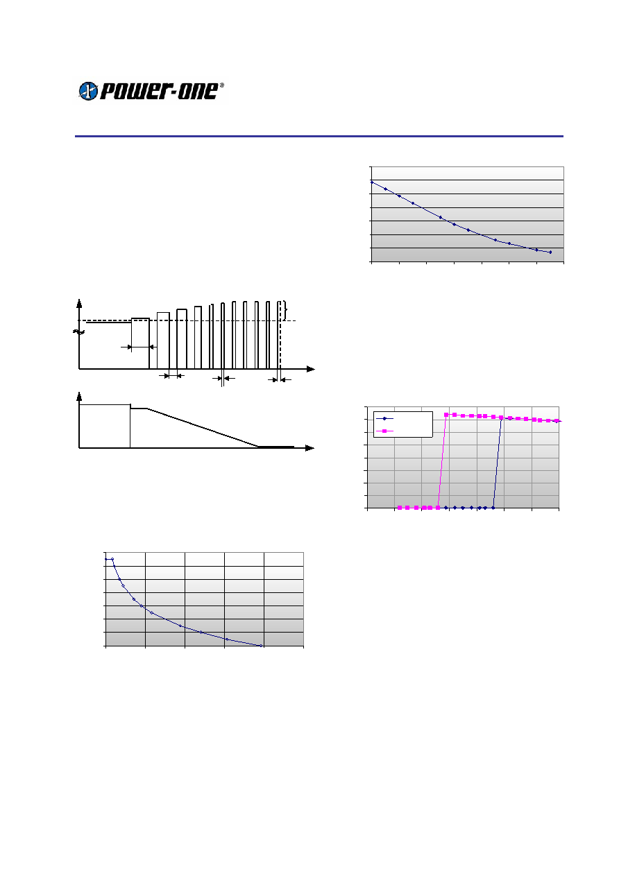
Output Over Current Protection
When the converter output is overloaded or
shorted, the module will go into hiccup mode. In
the hiccup mode, the brick is switched off
completely and restarted after a period of
approximately 550 ms. If the overload- or short
circuit is still present then, the converter will hiccup
until the overload is removed.
In order to be capable of starting large capacitive
loads, the converter provides a minimum on time
of approximately 30 ms.
Iolim
Iopeak
delta Io =
Iopeak- Io Lim
R Load
time
Io(t) Hiccup mode
off time = constant
550 ms typ
on - pulse duration
see graph
ton min 30 ms
110
Iolim
Short circuit
Nominal load
Overload
Up to 800 ms
Figure 37:
Hiccup Timing at Overload
With increasing overload, the peak output current
is slightly increased (delta Io typically up to 13 A).
At the same time the on pulse duration is reduced,
so that the total energy in an overload condition is
limited.
Typical "on-pulse" duration in overload
0
2
4
6
8
10
12
14
0
200
400
600
800
1000
Puls duration [ms]
delta
Io
=
(Io
P
eak
-
Io
Lim
)
[A]
Figure 38: Characteristic of over current protection
The off period allows hot tracks and loads to cool
down. The heating energy at the location of the
short circuit and in the PCB is proportional to Irms
2.
The following graph shows, that Irms
2 = Io pulse2
ton/T is reduced at high overload, which reduces
the danger of overheating and further damage to
the system.
Energy of the overload current
0
1000
2000
3000
4000
5000
6000
7000
100
102
104
106
108
110
112
114
Output current TXS100 [A]
Io
r
m
s
2
[A
2 ]
Figure 39: Function of Io rms
2, proportional to the
thermal energy at the overload location
Low Input Voltage
Input under voltage lookout
The unit is equipped with an input under voltage
lockout circuit, which ensures a defined start up
sequence.
0
0.1
0.2
0.3
0.4
0.5
0.6
0.7
0.8
29
30
31
32
33
34
35
36
Vi [V ]
Ii[A]
Turn-O n
Turn-O ff
Figure 40: TXS under voltage on / off hysteresis at
light load
Reduced output power of models ZB, ZD
The models ZB (1.8 V) and ZD (2.5 V) have a
reduced output power at minimum input voltage
when operated at highest base plate temperature
and increased Uo Set (over Trim or Sense). The
reduction is due to a duty cycle limitation of the
controller.
The rated output power of these two types [180 W
resp. 250 W] is available under the following
conditions:
Ui min >37 V: for TBP = 100 °C and Uo = Uo nom
Ui min >40 V: for TBP = 100 °C and Uo = 112 % Uo nom
At low input voltage, the ZB and ZD models will
switch off and soft restart periodically. The
operation is very similar to an under voltage
lockout or over current protection.
相關(guān)PDF資料 |
PDF描述 |
|---|---|
| TXS120ZY-P21V | 1-OUTPUT 144 W DC-DC REG PWR SUPPLY MODULE |
| TXS75ZY-P2R2V | 1-OUTPUT 90 W DC-DC REG PWR SUPPLY MODULE |
| TXS80ZD-3V | 1-OUTPUT 200 W DC-DC REG PWR SUPPLY MODULE |
| TPS61103RGE | 1.8 A SWITCHING REGULATOR, 800 kHz SWITCHING FREQ-MAX, PQCC24 |
| TPS2065DBVT | 1-CHANNEL POWER SUPPLY SUPPORT CKT, PDSO5 |
相關(guān)代理商/技術(shù)參數(shù) |
參數(shù)描述 |
|---|---|
| TXS18X | 制造商:YSTONE 制造商全稱:Yellow Stone Corp 功能描述:TAPED LED LAMP |
| TXS2-1.5V | 功能描述:低信號(hào)繼電器 - PCB 2 Form C 2A 30VDC 1.5VDC RoHS:否 制造商:NEC 觸點(diǎn)形式:2 Form C (DPDT-BM) 觸點(diǎn)電流額定值: 線圈電壓:5 V 最大開(kāi)關(guān)電流:1 A 線圈電流:1 A 線圈類型:Non-Latching 功耗:140 mW 端接類型:SMT 絕緣: 介入損耗: |
| TXS212J | 制造商:Panasonic Electric Works 功能描述: |
| TXS-212V | 制造商:Panasonic 功能描述:Bulk 制造商:Panasonic 功能描述:Electromechanical Relay DPDT 1A 12VDC 2.88KOhm Through Hole |
| TXS2-12V | 功能描述:低信號(hào)繼電器 - PCB 1A 12VDC DPDT NON-LATCHING PCB RoHS:否 制造商:NEC 觸點(diǎn)形式:2 Form C (DPDT-BM) 觸點(diǎn)電流額定值: 線圈電壓:5 V 最大開(kāi)關(guān)電流:1 A 線圈電流:1 A 線圈類型:Non-Latching 功耗:140 mW 端接類型:SMT 絕緣: 介入損耗: |
發(fā)布緊急采購(gòu),3分鐘左右您將得到回復(fù)。