- 您現(xiàn)在的位置:買賣IC網(wǎng) > PDF目錄368656 > TMP93CS40 Microcontroller PDF資料下載
參數(shù)資料
| 型號: | TMP93CS40 |
| 英文描述: | Microcontroller |
| 中文描述: | 微控制器 |
| 文件頁數(shù): | 14/16頁 |
| 文件大小: | 131K |
| 代理商: | TMP93CS40 |

TMP93CF76/CF77/CW76/CU76/CT76
2001-09-07
93CF76-186
4.4
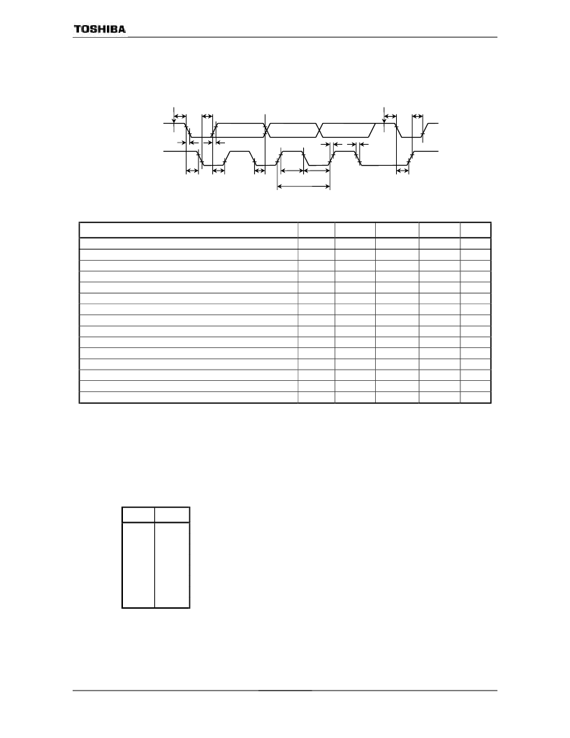
Serial Bus Interface Timing
(1) I
2
C bus Logic Timing
Parameter
Symbol
Min
Typ.
Max
Unit
SCL cycle
SCL low pulse width
SCL High pulse width
SDA Rising Time
SDA Falling Time
SCL Rising Time
SCL Falling Time
The time from start command write to start sheecense
Start condition hold time, start generation of the first clock after this
Delay time from SCL falling to data output
Set up time of data output for SCL rising
The time of holding data for SCL rising
The time from stop command write to starting stop sheecense
The time from SDA falling to SCL rising (during stop sheecense)
Stop condition set up time
t
CYCSCL
t
LOW
t
HIGH
t
RSDA
t
FSDA
t
RSCL
t
FSCL
t
GSTA1
t
GSTA2
t
ODAT1
t
SUODAT
t
HODAT
t
GSTP1
t
GSTP2
t
GSTP3
2
N
/fc
2
N-1
/fc
0
4/fc
2
N-2
/fc
2
N-1
/fc
s
s
s
s
s
s
s
s
s
s
s
s
s
s
s
2
N-1
/fc
2
N-1
/fc
(Note 1)
(Note 1)
(Note 1)
(Note 1)
2
N
/fc
(Note 2)
(Note 2)
(Note 3)
5/fc
2
N-1
/fc
Note 1:The time of rising/falling depend on the feature of bus interface.
Note 2:The worst case is at the first bit of slave address.
Note 3:The worst case is at the acknowledge bit.
Note 4:N: dividing value set by I2CCR1 <SCK 2:0>.
SCK
N
000
001
010
011
100
101
110
111
6
7
8
9
10
11
12
reserved
t
FSDA
t
RSDA
t
GSDA2
t
SUODAT
t
HDODAT
t
HIGH
t
LOW
t
ODAT1
t
GSTA1
t
RSCL
t
FSCL
t
GSTP2
t
GSTP1
t
GSTP3
SDA
SCL
Start Command
Stop Command
t
CYCSCL
相關(guān)PDF資料 |
PDF描述 |
|---|---|
| TMP93CT75F | Microcontroller |
| TMP93CT76 | Microcontroller |
| TMP93CU76 | Microcontroller |
| TMP93CW76 | Microcontroller |
| TMP93PM84F | 16-Bit Microcontroller |
相關(guān)代理商/技術(shù)參數(shù) |
參數(shù)描述 |
|---|---|
| TMP93CS40DF | 制造商:Toshiba America Electronic Components 功能描述:MCU 16BIT TLCS-900 CISC 64KB ROM 3.3V/5V 100LQFP - Tape and Reel |
| TMP93CS40F | 制造商:Toshiba America Electronic Components 功能描述:MCU 16BIT TLCS-900 CISC 64KB ROM 3.3V/5V 100PQFP - Tape and Reel |
| TMP93CS41 | 制造商:TOSHIBA 制造商全稱:Toshiba Semiconductor 功能描述:CMOS 16-Bit Microcontroller |
| TMP93CS41DF | 制造商:TOSHIBA 制造商全稱:Toshiba Semiconductor 功能描述:Quality And Reliability Assurance / Handling Precautions |
| TMP93CS41DFG(JOA) | 制造商:Toshiba America Electronic Components 功能描述: |
發(fā)布緊急采購,3分鐘左右您將得到回復(fù)。