- 您現(xiàn)在的位置:買賣IC網(wǎng) > PDF目錄361500 > TK75018DCTL (TOKO INC) SWITCHED CAPACITOR VOLTAGE CONVERTER WITH REGULATOR PDF資料下載
參數(shù)資料
| 型號: | TK75018DCTL |
| 廠商: | TOKO INC |
| 元件分類: | 穩(wěn)壓器 |
| 英文描述: | SWITCHED CAPACITOR VOLTAGE CONVERTER WITH REGULATOR |
| 中文描述: | SWITCHED CAPACITOR CONVERTER, 35 kHz SWITCHING FREQ-MAX, PDIP8 |
| 封裝: | DIP-8 |
| 文件頁數(shù): | 5/8頁 |
| 文件大小: | 91K |
| 代理商: | TK75018DCTL |
May 1999 TOKO, Inc.
Page 5
TK75018
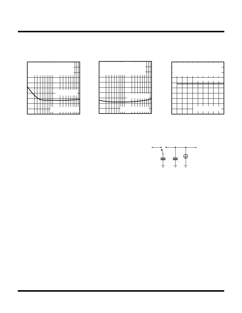
TYPICAL PERFORMANCE CHARACTERISTICS (CONT.)
V
fOSC (kHz)
1 10 100
2.0
1.0
0
INVERTER CONFIGURATION
CIN = 2.2 μF TANTALUM
COUT = 33 μF TANTALUM
IOUT =10 mA
OUTPUT VOLTAGE LOSS
VS.
OSCILLATOR FREQUENCY
Note 4 Test Circuit
V
OUTPUT VOLTAGE LOSS
VS.
OSCILLATOR FREQUENCY
fOSC (kHz)
1 10 100
2.0
1.0
0
INVERTER CONFIGURATION
CIN = 22 μF TANTALUM
COUT = 33 μF TANTALUM
IOUT =10 mA
Note 4 Test Circuit
V
1.0
CIN (μF)
0 20 40 60 80 100
0
0.8
0.4
0.2
0.6
IOUT = 10 mA
INVERTER CONFIGURATION
COUT = 33μF TANTALUM
fOSC = 25 kHz
OUTPUT VOLTAGE LOSS
VS.
INPUT CAPACITOR
Note 4 Test Circuit
As in any switched capacitor converter, the means of
conveying energy from input to output is done by charging
a capacitor between two potentials and then switching one
end of the capacitor to a different potential. By some
means of rectification, the other end of the capacitor is then
forced to dump charge into another capacitor at the
converter output, thereby conveying energy.
In a simple example shown in Figure 1, a capacitor C
1
has
one side tied to ground and another side charged by a
voltage source of potential V
1
. The non-grounded side of
C
1
is then switched over to be connected to one side of a
capacitor C
2
, which is at potential V
2
and referenced to
ground. V
2
represents the output of the converter. The
initial charge on C
1
is:
q
1
= C
1
x V
1
When the switch changes over to the V
2
side, C
1
is
discharged from potential V
1
to potential V
2
. After discharge
has occurred the charge on C
1
is then:
q
2
= C
1
x
V
2
This means that the net transfer of charge which has
occurred is:
q = q
1
– q
2
= C
1
(V
1
– V
2
)
THEORY OF OPERATION
FIGURE 1: SWITCHED CAPACITOR CIRCUIT
IL
V1
C2
V2
fO
C1
If the potential V
is sourcing a current I
L
, the charge will
have to be delivered at a rate:
O
= I
L
/
q = I
L
/ C
1
(V
1
– V
2
)
Thus, the higher the frequency, the more current that can
be supported by the converter output.
All else being ideal, the effective losses in the converter in
the energy conveyance process is identical to that of a
circuit consisting of a resistor between the potentials V
1
and V
, with the same load at the output side. This
equivalent resistor is simply:
R
EQUIV
= (V
1
– V
2
) / I
L
= 1 / (
O
x C
1
)
相關(guān)PDF資料 |
PDF描述 |
|---|---|
| TK75018 | SWITCHED CAPACITOR VOLTAGE CONVERTER WITH REGULATOR |
| TK75018MCTL | SWITCHED CAPACITOR VOLTAGE CONVERTER WITH REGULATOR |
| TK75018VCTL | SWITCHED CAPACITOR VOLTAGE CONVERTER WITH REGULATOR |
| TK75020 | ZVS RESONANT CONTROLLER |
| TK75020TL | ZVS RESONANT CONTROLLER |
相關(guān)代理商/技術(shù)參數(shù) |
參數(shù)描述 |
|---|---|
| TK75018MCTL | 制造商:TOKO 制造商全稱:TOKO, Inc 功能描述:SWITCHED CAPACITOR VOLTAGE CONVERTER WITH REGULATOR |
| TK75018VCTL | 制造商:TOKO 制造商全稱:TOKO, Inc 功能描述:SWITCHED CAPACITOR VOLTAGE CONVERTER WITH REGULATOR |
| TK75020 | 制造商:TOKO 制造商全稱:TOKO, Inc 功能描述:ZVS RESONANT CONTROLLER |
| TK75020TL | 制造商:TOKO 制造商全稱:TOKO, Inc 功能描述:ZVS RESONANT CONTROLLER |
| TK75020TL/75020 | 制造商:TOKO 制造商全稱:TOKO, Inc 功能描述:ZVS RESONANT CONTROLLER |
發(fā)布緊急采購,3分鐘左右您將得到回復(fù)。