- 您現(xiàn)在的位置:買賣IC網(wǎng) > PDF目錄98158 > TAS3218PZPR (TEXAS INSTRUMENTS INC) SPECIALTY CONSUMER CIRCUIT, PQFP100 PDF資料下載
參數(shù)資料
| 型號(hào): | TAS3218PZPR |
| 廠商: | TEXAS INSTRUMENTS INC |
| 元件分類: | 消費(fèi)家電 |
| 英文描述: | SPECIALTY CONSUMER CIRCUIT, PQFP100 |
| 封裝: | GREEN, PLASTIC, TQFP-100 |
| 文件頁(yè)數(shù): | 78/79頁(yè) |
| 文件大?。?/td> | 1263K |
| 代理商: | TAS3218PZPR |
第1頁(yè)第2頁(yè)第3頁(yè)第4頁(yè)第5頁(yè)第6頁(yè)第7頁(yè)第8頁(yè)第9頁(yè)第10頁(yè)第11頁(yè)第12頁(yè)第13頁(yè)第14頁(yè)第15頁(yè)第16頁(yè)第17頁(yè)第18頁(yè)第19頁(yè)第20頁(yè)第21頁(yè)第22頁(yè)第23頁(yè)第24頁(yè)第25頁(yè)第26頁(yè)第27頁(yè)第28頁(yè)第29頁(yè)第30頁(yè)第31頁(yè)第32頁(yè)第33頁(yè)第34頁(yè)第35頁(yè)第36頁(yè)第37頁(yè)第38頁(yè)第39頁(yè)第40頁(yè)第41頁(yè)第42頁(yè)第43頁(yè)第44頁(yè)第45頁(yè)第46頁(yè)第47頁(yè)第48頁(yè)第49頁(yè)第50頁(yè)第51頁(yè)第52頁(yè)第53頁(yè)第54頁(yè)第55頁(yè)第56頁(yè)第57頁(yè)第58頁(yè)第59頁(yè)第60頁(yè)第61頁(yè)第62頁(yè)第63頁(yè)第64頁(yè)第65頁(yè)第66頁(yè)第67頁(yè)第68頁(yè)第69頁(yè)第70頁(yè)第71頁(yè)第72頁(yè)第73頁(yè)第74頁(yè)第75頁(yè)第76頁(yè)第77頁(yè)當(dāng)前第78頁(yè)第79頁(yè)

SAP OUT
(Transmitter )
LRCLKOUT
(Recreation /
Normalization )
DPLL
(11x)
DSP_CLK
(135 MHz)
DIVBY
4
MICRO _CLK
(33 MHz)
MCLKOUT
256 Fs
2816 Fs
64 Fs
Fs
SCLKOUT
64Fs
SCLKIN
LRCLKOUT
Fs
LRCLKIN
MCLKIN
128 Fs
MCLKIN
DIVBY
2
256 Fs
CMS (ClockMaster /SlaveSelection )
DIVBY
2
DIVBY
4
DIVBY
8
DIVBY
512
0
1
0
1
0
1
0
1
CMS
SAP IN
SDIN 1
DatatoDSP Ch 1[23 :0 ]
ON (OutputNormalization
Enable )
SDOUT 1
DatafromDSP Ch 1 [23 :0]
SDIN 2
SDIN 3
DatatoDSP Ch 2[23 :0 ]
DatatoDSP Ch 3[23 :0 ]
DatatoDSP Ch 4[23 :0 ]
DatatoDSP Ch 5[23 :0 ]
DatatoDSP Ch 6[23 :0 ]
DatafromDSP Ch 2 [23 :0]
DatafromDSP Ch 3 [23 :0]
DatafromDSP Ch 4 [23 :0]
sdout 2
SPDIF_CLK
IM[1:0]
(SAP InputMode )
OM[1 :0]( SAP OutputMode )
SPDIF
Transmitter
ParallelDatafromDSP SPDIF _ L[23 :0]
ParallelDatafromDSP SPDIF _R[23 :0 ]
SPDIF _CONTROL _ REG_IN[]
spdif _tx_out
01
00
1*
SPDIF _IN
I2 CModule
DIVby 10
DIVby
(M+1)
DIVby 2^N
I2CSamplingClock
(N = 0)
SCL
SDA
I2CMasterSCL
Clock
(M = 8)
IM [1:0]
DigitalSignalProcessor
(DSP)
8051uC & Control
N[2:0]
M[2:0]
CMS
IW[1:0]
( SAP InputWordSize )
OW[1 :0]( SAP OutputWordSize )
OUTMUX [1 :0]
(AudioOutputSelect - ControlBits [1 :0]
fromSPDIFControlRegister : 0x16 )
SPDIF_OUT /
SDOUT2
0
1
SPDIF_MUTE
0
(MuteControlRegister : 0x09)
SAPOUT _MUTE [1 :0]
OSC
512Fs
Digital Audio Interface
SLES235 – JULY 2008 ....................................................................................................................................................................................................... www.ti.com
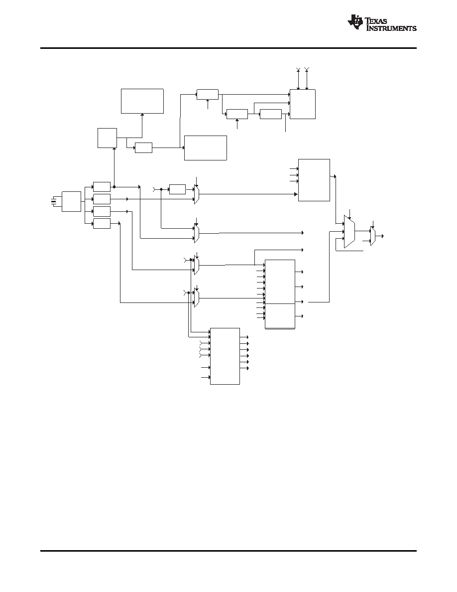
Figure 3. Clocking System
The TAS3218 has three digital inputs that accept discrete I2S, discrete left-justified, and discrete right-justified
PCM data.
The TAS3218 has two digital outputs that provide discrete I2S, discrete left-justified, and discrete right-justified
PCM data.The second digital output can also be configured to provide S/PDIF encoded PCM data.
The TAS3218 has a SPDIF input which is capable of routing an S/PDIF encoded signal through the device. This
input is not processed by the digital audio processor (DAP) The clocking system for the device is illustrated in
8
Copyright 2008, Texas Instruments Incorporated
Product Folder Link(s): TAS3218
相關(guān)PDF資料 |
PDF描述 |
|---|---|
| TAS3218PZP | SPECIALTY CONSUMER CIRCUIT, PQFP100 |
| TAS5000PFB | SPECIALTY CONSUMER CIRCUIT, PQFP48 |
| TAS5000PFBG4 | SPECIALTY CONSUMER CIRCUIT, PQFP48 |
| TAS5001PFB | SPECIALTY CONSUMER CIRCUIT, PQFP48 |
| TAS5001IPFBR | SPECIALTY CONSUMER CIRCUIT, PQFP48 |
相關(guān)代理商/技術(shù)參數(shù) |
參數(shù)描述 |
|---|---|
| TAS-3225A | 制造商:TEW 功能描述: |
| TAS-3225A 44.000KHZ | 制造商:TEW 功能描述: |
| TAS-3225J 13.56MHz }20ppm/22pF | 制造商:Tokyo Denpa 功能描述:13.560000MHz }20ppm }15ppm 22pF 3.2~2.5~0.55mm +85 -30 3.2mm 2.5mm 0.55mm Cut Tape |
| TAS-3225J 14.7456MHz }20ppm/18pF | 制造商:Tokyo Denpa 功能描述:14.745600MHz }20ppm }15ppm 18pF 3.2~2.5~0.55mm +85 -30 3.2mm 2.5mm 0.55mm Cut Tape |
| TAS-3225J 16MHz }20ppm/16pF | 制造商:Tokyo Denpa 功能描述:16.000000MHz }20ppm }15ppm 16pF 3.2~2.5~0.55mm +85 -30 3.2mm 2.5mm 0.55mm Cut Tape |
發(fā)布緊急采購(gòu),3分鐘左右您將得到回復(fù)。