- 您現(xiàn)在的位置:買賣IC網(wǎng) > PDF目錄373529 > T5753-6AQ (ATMEL CORP) UHF ASK/FSK TRANSMITTER PDF資料下載
參數(shù)資料
| 型號(hào): | T5753-6AQ |
| 廠商: | ATMEL CORP |
| 元件分類: | 通信及網(wǎng)絡(luò) |
| 英文描述: | UHF ASK/FSK TRANSMITTER |
| 中文描述: | SPECIALTY TELECOM CIRCUIT, PDSO8 |
| 封裝: | TSSOP-8 |
| 文件頁(yè)數(shù): | 4/13頁(yè) |
| 文件大?。?/td> | 213K |
| 代理商: | T5753-6AQ |
第1頁(yè)第2頁(yè)第3頁(yè)當(dāng)前第4頁(yè)第5頁(yè)第6頁(yè)第7頁(yè)第8頁(yè)第9頁(yè)第10頁(yè)第11頁(yè)第12頁(yè)第13頁(yè)
4
T5753
4510F–RKE–07/04
Functional
Description
If ENABLE = L and the PA_ENABLE = L, the circuit is in standby mode consuming only
a very small amount of current so that a lithium cell used as power supply can work for
several years.
With ENABLE = H the XTO, PLL and the CLK driver are switched on. If PA_ENABLE
remains L only the PLL and the XTO is running and the CLK signal is delivered to the
microcontroller. The VCO locks to 32 times the XTO frequency.
With ENABLE = H and PA_ENABLE = H the PLL, XTO, CLK driver and the power
amplifier are on. With PA_ENABLE the power amplifier can be switched on and off,
which is used to perform the ASK modulation.
ASK Transmission
The T5753 is activated by ENABLE = H. PA_ENABLE must remain L for
typically
≥
3 ms, then the CLK signal can be taken to clock the microcontroller and the
output power can be modulated by means of Pin PA_ENABLE. After transmission
PA_ENABLE is switched to L and the microcontroller switches back to internal clocking.
The T5753 is switched back to standby mode with ENABLE = L.
FSK Transmission
The T5753 is activated by ENABLE = H. PA_ENABLE must remain L for
typically
≥
3 ms, then the CLK signal can be taken to clock the microcontroller and the
power amplifier is switched on with PA_ENABLE = H. The chip is then ready for FSK
modulation. The microcontroller starts to switch on and off the capacitor between the
XTAL load capacitor and GND with an open-drain output port, thus changing the refer-
ence frequency of the PLL. If the switch is closed, the output frequency is lower than if
the switch is open. After transmission PA_ENABLE is switched to L and the microcon-
troller switches back to internal clocking. The T5753 is switched back to standby mode
with ENABLE = L.
The accuracy of the frequency deviation with XTAL pulling method is about ±25% when
the following tolerances are considered.
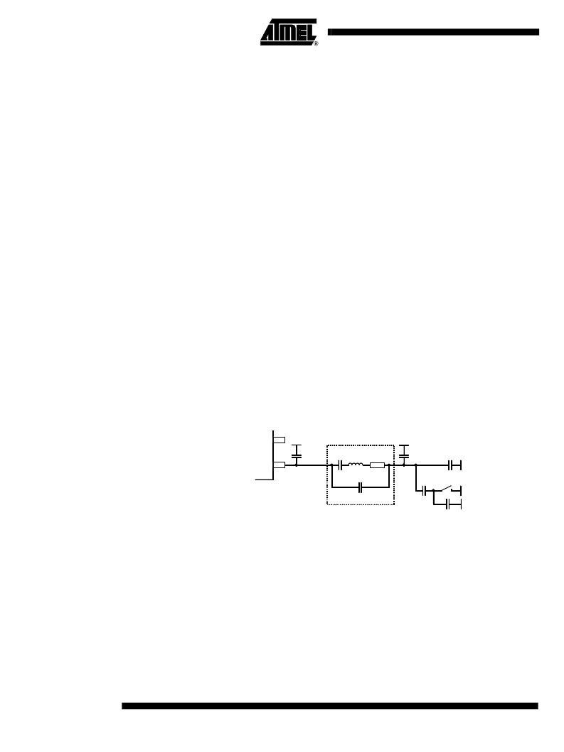
Figure 4.
Tolerances of Frequency Modulation
~
V
S
Using C
4
= 8.2 pF ± 5%, C
5
= 10 pF ± 5%, a switch port with C
Switch
= 3 pF ± 10%, stray
capacitances on each side of the crystal of C
Stray1
= C
Stray2
= 1 pF ± 10%, a parallel
capacitance of the crystal of C
0
= 3.2 pF ± 10% and a crystal with C
M
= 13 fF ± 10%, an
FSK deviation of ±21.5 kHz typical with worst case tolerances of ±16.25 kHz to
±28.01 kHz results.
CLK Output
An output CLK signal is provided for a connected microcontroller, the delivered signal is
CMOS compatible if the load capacitance is lower than 10 pF.
Clock Pulse Take-over
The clock of the crystal oscillator can be used for clocking the microcontroller. Atmel’s
ATARx9x has the special feature of starting with an integrated RC-oscillator to switch on
the T5753 with ENABLE = H, and after 1 ms to assume the clock signal of the transmis-
sion IC, so that the message can be sent with crystal accuracy.
~
XTAL
C
Stray1
C
M
L
M
R
S
C
0
C
Stray2
C
4
C
5
Crystal equivalent circuit
C
Switch
相關(guān)PDF資料 |
PDF描述 |
|---|---|
| T5754 | UHF ASK/FSK TRANSMITTER |
| T5754-6AQ | UHF ASK/FSK TRANSMITTER |
| T5760 | UHF ASK/FSK Receiver |
| T5760-TG | UHF ASK/FSK Receiver |
| T5761 | UHF ASK/FSK Receiver |
相關(guān)代理商/技術(shù)參數(shù) |
參數(shù)描述 |
|---|---|
| T5753-6AQJ | 功能描述:射頻發(fā)射器 ASK/FSK Transmitter 310 - 330 MHz RoHS:否 制造商:Micrel 類型:ASK Transmitter 封裝 / 箱體:SOT-23-6 工作頻率:300 MHz to 450 MHz 封裝:Reel |
| T5753-6AQJ 71 | 制造商:Atmel Corporation 功能描述:UHF ASK/FSK TRANSMITTER 315 MH |
| T5753-6AQJ 71 | 制造商:Atmel Corporation 功能描述:UHF ASK/FSK TRANSMITTER 315 MHZ - Tape and Reel |
| T5753-6AQJ-66 | 功能描述:射頻發(fā)射器 UHF ASK/FSK Trnsmttr 315 MHz RoHS:否 制造商:Micrel 類型:ASK Transmitter 封裝 / 箱體:SOT-23-6 工作頻率:300 MHz to 450 MHz 封裝:Reel |
| T5753-6AQJ71 | 功能描述:射頻發(fā)射器 UHF ASK/FSK Transmitter 315MHz RoHS:否 制造商:Micrel 類型:ASK Transmitter 封裝 / 箱體:SOT-23-6 工作頻率:300 MHz to 450 MHz 封裝:Reel |
發(fā)布緊急采購(gòu),3分鐘左右您將得到回復(fù)。