- 您現(xiàn)在的位置:買(mǎi)賣IC網(wǎng) > PDF目錄9662 > SY87739LHY TR (Micrel Inc)IC SYNTHESIZER FRACTION N 32TQFP PDF資料下載
參數(shù)資料
第1頁(yè)第2頁(yè)第3頁(yè)第4頁(yè)第5頁(yè)第6頁(yè)第7頁(yè)第8頁(yè)第9頁(yè)第10頁(yè)第11頁(yè)第12頁(yè)第13頁(yè)第14頁(yè)第15頁(yè)當(dāng)前第16頁(yè)第17頁(yè)

Micrel, Inc.
SY87739L
June 2011
8
M9999-061511
hbwhelp@micrel.com
Whereas P sets the integer part of the multiplication
factor from input to output frequency, the control circuit
determines the fractional part. By mixing the output of
the P and P–1 dividers correctly, the control circuit can
fashion any output frequency from P–1 times the input to
P times the input, as long as that ratio can be expressed
as a ratio of integers.
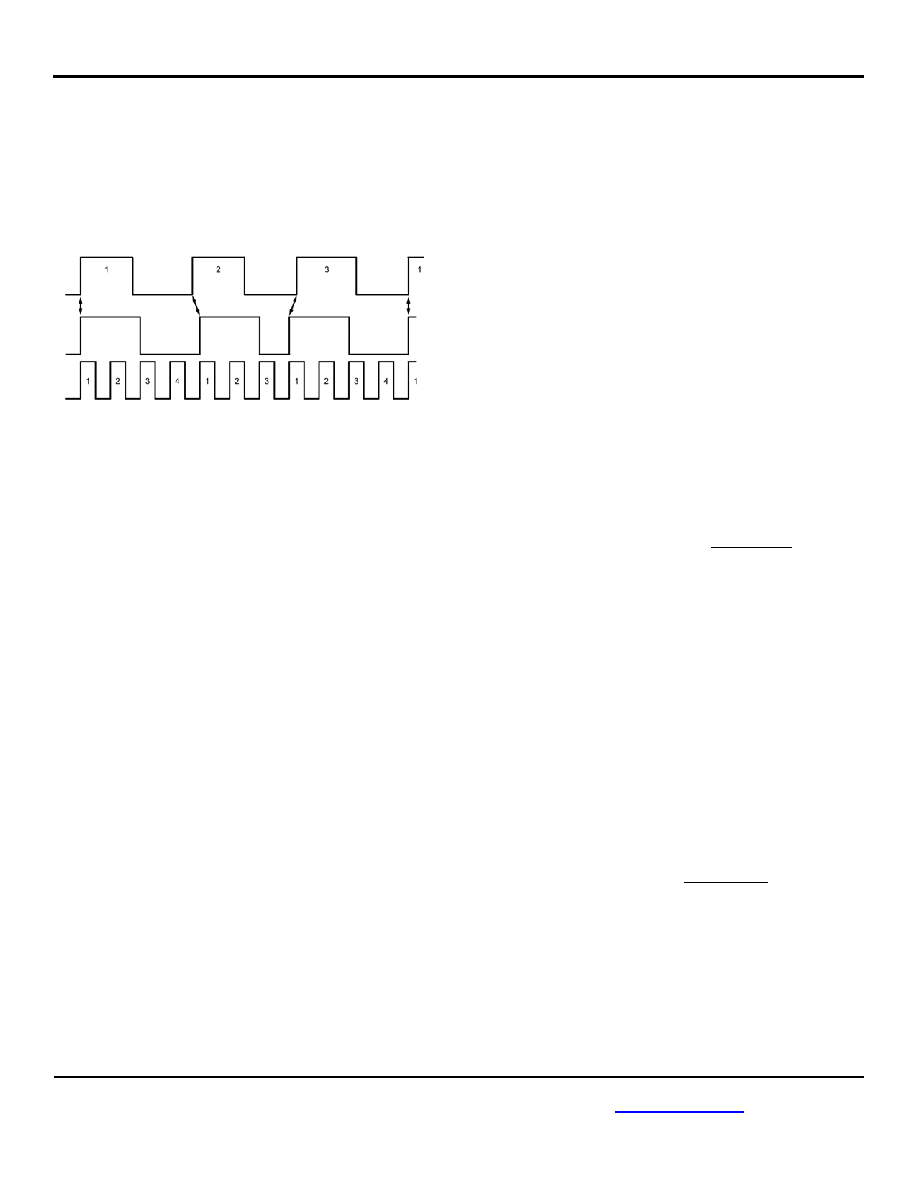
Figure 2. 11/3 Example
Figure 2 shows an example generating an output
frequency 3 2/3 times the input frequency. Since the
output frequency is between 3 and 4 times the input, P is
set to 4. We need to select the P divider twice, and
select the P–1 divider once. Multiplying by 4 two times
out of three, and multiplying by 3 one time out of three,
averages to a multiplication of 32/3.
The top waveform is the reference input. The bottom
waveform is the multiplied output. The waveform in the
middle shows those edges from the output that most
closely matches a corresponding reference waveform
edge.
The control circuit must generate a repeating pattern to
the mux of something like “101”, so that the P divider is
selected twice, and the P–1 divider is selected once,
every three reference edges.
Fractional-N Phase-Frequency Detector
This circuit, besides generating “pump up” and “pump
down” signals, also generates delta phase signals for
use by the lock detect circuit.
This detector circuit also accepts a gating signal from the
fractional-N control block. When gated, the phase
detector generates neither pump up nor pump down
pulses.
or (408) 955-1690
Fractional-N Charge Pump
This circuit converts the “pump up” and “pump down”
signals from the phase-frequency detector into current
pulses. An external loop filter integrates these current
pulses into a control voltage.
Charge pump current is selectable. This modifies loop
gain as follows:
During acquisition of the reference, the charge
pump current is fixed at 20A. Once the
acquisition sequencer has completed center
frequency trimming, then it changes the current
of this charge pump to 50A.
Fractional-N VCO
This circuit converts the voltage integrated by the
external loop filter into a digital clock stream. The
frequency of this clock varies based on this control
voltage. This VCO has a coarse and a fine input, with a
combined range of 540MHz to 729MHz. The coarse
input trims the VCO, as described below, so that its
center frequency rests near the target frequency to
generate. The fine adjustment forms part of the closed
loop. VCO gain is nominally 200MHz per volt.
Fractional-N P/P-1 Divider
This is the main divider for the fractional-N loop. The
logical value of the output of the control block (Figure 1)
defines whether the divider divides by P (values shown
in Table 1) or by P–1. The expression for the fractional
division becomes:
Fractional Division =
()
+
P
1
P
1
P
Q
P
Where QP is the number of reference clock periods
during which the divider must divide by P and QP-1 is the
number of reference clock periods during which the
divider must divide by P–1.
Care should be exercised when selecting the value of P
(Table 1) so that the voltage-controlled oscillator (VCO)
of the fractional-N PLL is not driven out of range. The
following conditions must be met:
fVCO(MIN) < fREF × Fractional Division < fVCO(MAX)
or
fVCO(MIN) < fREF ×
(
)
+
P
1
P
1
P
Q
P
< f
VCO(MAX)
where:
fVCO(MIN) = 540MHz
fVCO(MAX) = 729MHz
fREF = Frequency of the reference clock
相關(guān)PDF資料 |
PDF描述 |
|---|---|
| SY87729LHY TR | IC SYNTHESIZER FRACTION N 32TQFP |
| MS3100A28-21P | CONN RCPT 37POS WALL MNT W/PINS |
| MS27497E22F21P | CONN RCPT 21POS WALL MNT W/PINS |
| MS27497E14B37PA | CONN RCPT 37POS WALL MNT W/PINS |
| MS3450W12S-2S | CONN RCPT 2POS WALL MNT W/SCKT |
相關(guān)代理商/技術(shù)參數(shù) |
參數(shù)描述 |
|---|---|
| SY87813L | 制造商:MICREL 制造商全稱:Micrel Semiconductor 功能描述:3.3V, 28Mbps to 1.3Gbps AnyRate Clock and Data Recovery |
| SY87813L_06 | 制造商:MICREL 制造商全稱:Micrel Semiconductor 功能描述:3-Port 10/100 Integrated Switch with PHY and Frame Buffer |
| SY87813LHG | 功能描述:計(jì)時(shí)器和支持產(chǎn)品 3.3V Any-Rate 32-1250 Mbps CDR (I Temp, Green/32 Pin EP-TQFP/bulk) RoHS:否 制造商:Micrel 類型:Standard 封裝 / 箱體:SOT-23 內(nèi)部定時(shí)器數(shù)量:1 電源電壓-最大:18 V 電源電壓-最小:2.7 V 最大功率耗散: 最大工作溫度:+ 85 C 最小工作溫度:- 40 C 封裝:Reel |
| SY87813LHG TR | 功能描述:計(jì)時(shí)器和支持產(chǎn)品 3.3V Any-Rate 32-1250 Mbps CDR (PbSn/I Temp/32 Pin EP-TQFP/T+R) RoHS:否 制造商:Micrel 類型:Standard 封裝 / 箱體:SOT-23 內(nèi)部定時(shí)器數(shù)量:1 電源電壓-最大:18 V 電源電壓-最小:2.7 V 最大功率耗散: 最大工作溫度:+ 85 C 最小工作溫度:- 40 C 封裝:Reel |
| SY87813LHGTR | 制造商:MICREL 制造商全稱:Micrel Semiconductor 功能描述:3.3V, 28Mbps to 1.3Gbps AnyRate Clock and Data Recovery |
發(fā)布緊急采購(gòu),3分鐘左右您將得到回復(fù)。
