- 您現(xiàn)在的位置:買賣IC網(wǎng) > PDF目錄372185 > SP505AN Multi-Protocol Serial Transceivers PDF資料下載
參數(shù)資料
| 型號(hào): | SP505AN |
| 英文描述: | Multi-Protocol Serial Transceivers |
| 中文描述: | 多協(xié)議串行收發(fā)器 |
| 文件頁(yè)數(shù): | 21/35頁(yè) |
| 文件大小: | 495K |
| 代理商: | SP505AN |
第1頁(yè)第2頁(yè)第3頁(yè)第4頁(yè)第5頁(yè)第6頁(yè)第7頁(yè)第8頁(yè)第9頁(yè)第10頁(yè)第11頁(yè)第12頁(yè)第13頁(yè)第14頁(yè)第15頁(yè)第16頁(yè)第17頁(yè)第18頁(yè)第19頁(yè)第20頁(yè)當(dāng)前第21頁(yè)第22頁(yè)第23頁(yè)第24頁(yè)第25頁(yè)第26頁(yè)第27頁(yè)第28頁(yè)第29頁(yè)第30頁(yè)第31頁(yè)第32頁(yè)第33頁(yè)第34頁(yè)第35頁(yè)
21
Rev: A Date: 1/27/04
SP505 Multi–Mode Serial Transceiver
Copyright 2004 Sipex Corporation
serial interface. As the operating mode of the
receivers is changed, the electrical characteris-
tics will change to support the requirements of
clock, data, and control line receivers.
Table 2
shows the mode of each receiver in the different
interface modes that can be selected.
There are three basic types of receiver circuits
— V.28, V.10, and V.11.
V.28 Receivers
The V.28 receiver is single–ended and accepts
V.28 signals from the V.28 driver. The V.28
receiver has an operating voltage range of +15V
and can receive signals down to +3V. The input
sensitivity complies with RS-232 and V.28 speci-
fications at +3V. The input impedance is 3k
to
7k
in accordance to RS-232 and V.28 over a
+15V input range. The receiver output pro-
duces a TTL/CMOS signal with a +2.4V mini-
mum for a logic "1" and a +0.8V maximum for
a logic "0". V.28 receivers are used in RS-232
mode for all data, clock and control signals.
They are also used in V.35 mode for control line
signals: CTS, DSR, LL, and RL. The V.28
receivers can operate to at least 120kbps.
V.10 Receivers
The V.10 receivers are also single–ended as
with the V.28 receivers but have an input thresh-
old as low as +200mV. The input impedance is
guaranteed to be greater than 4K
, with an
operating voltage range of +7V. The V.10 re-
ceivers can operate to at least 120kbps. V.10
receivers are used in RS-449, EIA-530, EIA-
530A and V.36 modes as Category II signals as
indicated by their corresponding specifications.
V.11 Receivers
The third type of receiver is a differential which
supports V.11 and RS-485 signals. This re-
ceiver has a typical input impedance of 10k
and a typical differential threshold of +200mV,
which complies with the V.11 specification.
Since the characteristics of the V.11 receivers
are actually subsets of RS-485, the V.11 receiv-
ers can accept RS-485 signals. However, these
receivers cannot support 32-transceivers on the
signal bus due to the lower input impedance as
specified in the RS-485 specification. Three
receivers (RxD, RxC, and SCT) include a typi-
cal 120
cable termination resistor across the A
and B inputs. The resistor for the three receivers
is switched on when the
SP505
is configured in
a mode which uses V.11 receivers. The V.11
cable termination resistor is switched off when
the receiver is disabled or in another operating
mode not using V.11 receivers. The V.11 re-
ceivers are used in X.21, RS-449, EIA-530,
EIA-530A and V.36 as Category I signals for
receiving clock, data, and some control line
signals not covered by Category II V.10 circuits.
The differential receivers can receive signals
over 10Mbps.
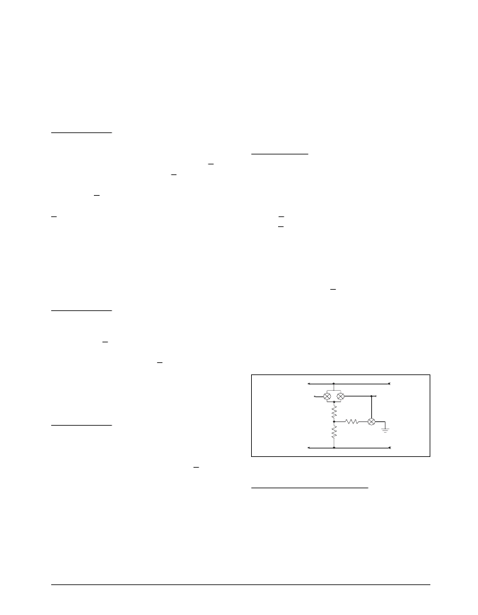
V.35 Receiver
The V.11 receivers are also used for the V.35
mode. Unlike the older implementations of
differential receivers used for V.35, the
SP505
contains an internal resistor termination net-
work that ensures a V.35 input impedance of
100
(+10
) and a short-circuit impedance of
150
(+15
). The traditional V.35 implemen-
tations required external termination resistors to
achieve the proper V.35 impedances. The inter-
nal network is connected via low on-resistance
FET switches when the decoder is changed to
V.35 mode. These FET switches can accept
input signals of up to +15V without any forward
biasing and other parasitic affects. The V.35
termination resistor network is switched off
when the receiver is disabled either by the de-
coder or receiver enable pin. The termination
network is transparent when all other modes are
selected. The V.35 receivers can operate over
10Mbps.
Receiver Enable and Output
Only one receiver includes an enable line. The
SCTEN input for the SCT receiver can enable or
tri-state the output of the receiver. When the pin
is at a logic "0", the receiver output is high
impedance and any input termination internal
connected is switched off. The inputs will be at
approximately 10k
during tri-state.
V.11 TERMINATION
MODE [0100]
V.35 MODE
R
IN
[a]
R
IN
[b]
To Non-Inverting
To Inverting Input
r
ON
= 20
r
ON
= 1
51
51
124
r
ON
= 1
Figure 51. Simplified R
IN
Termination Circuit
相關(guān)PDF資料 |
PDF描述 |
|---|---|
| SP505BCF | WAN Multi-Mode Serial Transceiver |
| SP505BCM | WAN Multi-Mode Serial Transceiver |
| SP505CF | Multi-Protocol Serial Transceivers |
| SP505EB | Multi-Protocol Serial Transceivers |
| SP505EK | Multi-Protocol Serial Transceivers |
相關(guān)代理商/技術(shù)參數(shù) |
參數(shù)描述 |
|---|---|
| SP505BCF | 制造商:Exar Corporation 功能描述:Line Transceiver, 7-Driver, 7-Receiver, 80 Pin, Plastic, QFP |
| SP505BCM | 制造商:SIPEX 制造商全稱:Sipex Corporation 功能描述:WAN Multi-Mode Serial Transceiver |
| SP505BCM-L | 功能描述:總線收發(fā)器 WAN Multi-Mode Serial RoHS:否 制造商:Fairchild Semiconductor 邏輯類型:CMOS 邏輯系列:74VCX 每芯片的通道數(shù)量:16 輸入電平:CMOS 輸出電平:CMOS 輸出類型:3-State 高電平輸出電流:- 24 mA 低電平輸出電流:24 mA 傳播延遲時(shí)間:6.2 ns 電源電壓-最大:2.7 V, 3.6 V 電源電壓-最小:1.65 V, 2.3 V 最大工作溫度:+ 85 C 封裝 / 箱體:TSSOP-48 封裝:Reel |
| SP505CF | 制造商:SIPEX 制造商全稱:Sipex Corporation 功能描述:Multi-Protocol Serial Transceivers |
| SP505EB | 制造商:SIPEX 制造商全稱:Sipex Corporation 功能描述:Multi-Protocol Serial Transceivers |
發(fā)布緊急采購(gòu),3分鐘左右您將得到回復(fù)。