- 您現(xiàn)在的位置:買賣IC網(wǎng) > PDF目錄374699 > SAF-C505L-4EM (INFINEON TECHNOLOGIES AG) 8-bit CMOS Microcontroller PDF資料下載
參數(shù)資料
| 型號: | SAF-C505L-4EM |
| 廠商: | INFINEON TECHNOLOGIES AG |
| 元件分類: | 8位微控制器 |
| 英文描述: | 8-bit CMOS Microcontroller |
| 中文描述: | 8位CMOS微控制器 |
| 文件頁數(shù): | 43/85頁 |
| 文件大小: | 487K |
| 代理商: | SAF-C505L-4EM |
第1頁第2頁第3頁第4頁第5頁第6頁第7頁第8頁第9頁第10頁第11頁第12頁第13頁第14頁第15頁第16頁第17頁第18頁第19頁第20頁第21頁第22頁第23頁第24頁第25頁第26頁第27頁第28頁第29頁第30頁第31頁第32頁第33頁第34頁第35頁第36頁第37頁第38頁第39頁第40頁第41頁第42頁當前第43頁第44頁第45頁第46頁第47頁第48頁第49頁第50頁第51頁第52頁第53頁第54頁第55頁第56頁第57頁第58頁第59頁第60頁第61頁第62頁第63頁第64頁第65頁第66頁第67頁第68頁第69頁第70頁第71頁第72頁第73頁第74頁第75頁第76頁第77頁第78頁第79頁第80頁第81頁第82頁第83頁第84頁第85頁
C505L
Data Sheet
41
06.99
10-Bit A/D Converter
The C505L includes a high performance / high speed 10-bit A/D-Converter (ADC) with 8 analog
input channels. It operates with a successive approximation technique and uses self calibration
mechanisms for reduction and compensation of offset and linearity errors. The A/D converter
provides the following features:
– 8 multiplexed input channels (port 1), which can also be used as digital inputs/outputs
– 10-bit resolution
– Single or continuous conversion mode
– Internal start-of-conversion trigger capability
– Interrupt request generation after each conversion
– Using successive approximation conversion technique via a capacitor array
– Built-in hidden calibration of offset and linearity errors
The 10-bit ADC uses two clock signals for operation: the conversion clock
f
ADC
(= 1/
t
ADC
) and the
input clock
f
IN
(= 1/
t
IN
).
f
ADC
is derived from the C505L system clock
f
OSC
which is applied at the
XTAL pins. The input clock
f
IN
is equal to
f
OSC
The conversion
f
ADC
clock is limited to a maximum
frequency of 2 MHz. Therefore, the ADC clock prescaler must be programmed to a value which
assures that the conversion clock does not exceed 2 MHz. The prescaler ratio is selected by the
bits ADCL1 and ADCL0 of SFR ADCON1.
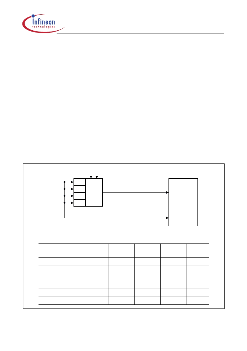
Figure 19
10-Bit A/D Converter Clock Selection
MCS03867
32
16
8
4
÷
MUX
ADCL0
ADCL1
OSC
f
Clock Prescaler
Conversion Clock f
ADC
Input Clock
IN
f
A/D
Converter
Conditions:
f
ADCmax
= 2 MHz
f
IN
=f
OSC
=
1
CLP
÷
÷
÷
MCUSystemClock
Rate (
f
OSC
)
2 MHz
f
IN
[MHz]
Prescaler
Ratio
÷
4
÷
4
÷
4
÷
8
÷
8
÷
16
f
ADC
[MHz]
ADCL1
ADCL0
2
0.5
0
0
6 MHz
6
1.5
0
0
8 MHz
8
2
0
0
12 MHz
12
1.5
0
1
16 MHz
16
2
0
1
20 MHz
20
1.25
1
0
相關PDF資料 |
PDF描述 |
|---|---|
| SAB-C505 | 8-bit CMOS Microcontroller |
| SAF-C505L | 8-bit CMOS Microcontroller |
| SAB-C505L | 8-bit CMOS Microcontroller |
| SAF-C505 | 8-bit CMOS Microcontroller |
| SAFC505 | 8-bit CMOS Microcontroller |
相關代理商/技術參數(shù) |
參數(shù)描述 |
|---|---|
| SAF-C505-LM | 制造商:Rochester Electronics LLC 功能描述:- Bulk |
| SAFC5084EM | 制造商:Infineon Technologies AG 功能描述:MCU 8-bit C500 8051 CISC 32KB EPROM 5V 64-Pin MQFP |
| SAFC5084EMTR | 制造商:Infineon Technologies AG 功能描述:MCU 8-Bit C500 8051 CISC 32KB EPROM 5V 64-Pin MQFP T/R |
| SAFC5084EMTR-AA | 制造商:Infineon Technologies AG 功能描述:IC 8-BIT MCU |
| SAFC5084EMTR-AB | 制造商:Infineon Technologies AG 功能描述:IC,8-BIT MCU,0/70|C, P-MQFP-64 |
發(fā)布緊急采購,3分鐘左右您將得到回復。