- 您現(xiàn)在的位置:買賣IC網(wǎng) > PDF目錄372109 > SAA4951WP (NXP SEMICONDUCTORS) Memory controller PDF資料下載
參數(shù)資料
| 型號(hào): | SAA4951WP |
| 廠商: | NXP SEMICONDUCTORS |
| 元件分類: | 消費(fèi)家電 |
| 英文描述: | Memory controller |
| 中文描述: | SPECIALTY CONSUMER CIRCUIT, PQCC44 |
| 封裝: | PLASTIC, SOT-187-2, MO-047AC, LCC-44 |
| 文件頁(yè)數(shù): | 12/25頁(yè) |
| 文件大?。?/td> | 95K |
| 代理商: | SAA4951WP |
第1頁(yè)第2頁(yè)第3頁(yè)第4頁(yè)第5頁(yè)第6頁(yè)第7頁(yè)第8頁(yè)第9頁(yè)第10頁(yè)第11頁(yè)當(dāng)前第12頁(yè)第13頁(yè)第14頁(yè)第15頁(yè)第16頁(yè)第17頁(yè)第18頁(yè)第19頁(yè)第20頁(yè)第21頁(yè)第22頁(yè)第23頁(yè)第24頁(yè)第25頁(yè)

April 1994
12
Philips Semiconductors
Preliminary specification
Memory controller
SAA4951
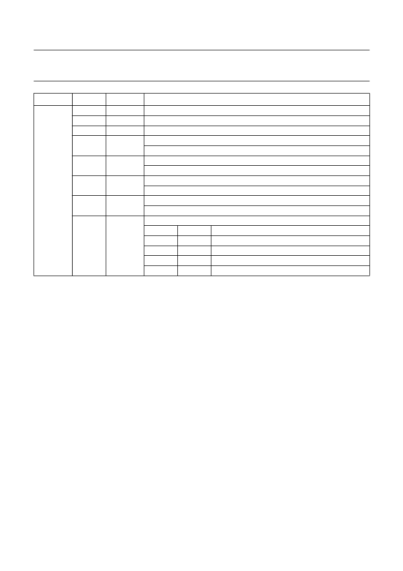
MODE1
0 (LSB)
1
2
3
DR
STPWM1
STPWM2
MC1
display raster
stop writing to memory 1: still picture mode
stop writing to memory 2: still picture mode
memory configuration bit 1
0: two field memories; 1: one field memory
golden scart
0: normal IPQ mode; 1: golden scart input
for external mode (13.5 MHz input clock) only:
0 = 50 Hz, 864 clock cycles per line; 1 = 60 Hz, 858 clock cycles per line
horizontal reference pulse BLNA and clock LLA from external source
0: internal (PLL); 1: external
vertical frequency select
VFS
DR
0
0
100 Hz (312.5 lines) ABAB raster
0
1
100 Hz (313/312.5/312/312.5 lines) AABB raster
1
0
50 Hz (625 lines) 1:1, non-interlaced
1
1
50 Hz (1250 lines) 2:1, interlaced
4
GSC
5
CCIR60
6
EXTLLA
7
VFS
display mode
REGISTER
BIT
NAME
REMARKS
Description of acquisition part
LLA
This is the main input clock pulse for the acquisition side of
the memory controller generated by an external PLL
circuit. Depending on the chosen system application LLA
runs on the different frequencies of 12/13.5/16/18 MHz.
The PLL circuit is controlled by the analog burst key pulse
ABK provided by an inserted synchronization circuit (i. e.
TDA2579) and the horizontal reference signal HRA
supplied by the SAA4951 circuit.
WEXT
External write enable input for digital colour decoder
applications, where the write enable signal is generated by
the digital colour decoder. This signal is simply sampled by
LLA and fed out at WE1.
SWC1
The acquisition clock input signal LLA is connected
through the memory controller circuit. LLA is internally
buffered and put out as serial write clock SWC1 for the
memory 1. Additionally SWC1 is used as a clock signal for
the three AD-converters and for the formatter function.
ALDUV/VB
The output signal ALDUV (analog load for the
chrominance signals U and V) controls the formation of the
8-bit digital data information of the chrominance signals U
and V.
相關(guān)PDF資料 |
PDF描述 |
|---|---|
| SAA4952WP | Memory controller |
| SAA4955 | 2.9-Mbit field memory |
| SAA4955TJ | 2.9-Mbit field memory |
| SAA4956TJ | 2.9-Mbit field memory with noise reduction |
| SAA4960 | Integrated PAL comb filter |
相關(guān)代理商/技術(shù)參數(shù) |
參數(shù)描述 |
|---|---|
| SAA4952WP | 制造商:PHILIPS 制造商全稱:NXP Semiconductors 功能描述:Memory controller |
| SAA4955 | 制造商:PHILIPS 制造商全稱:NXP Semiconductors 功能描述:2.9-Mbit field memory |
| SAA4955TJ | 制造商:PHILIPS 制造商全稱:NXP Semiconductors 功能描述:2.9-Mbit field memory |
| SAA4956TJ | 制造商:PHILIPS 制造商全稱:NXP Semiconductors 功能描述:2.9-Mbit field memory with noise reduction |
| SAA4960 | 制造商:PHILIPS 制造商全稱:NXP Semiconductors 功能描述:Integrated PAL comb filter |
發(fā)布緊急采購(gòu),3分鐘左右您將得到回復(fù)。