- 您現(xiàn)在的位置:買賣IC網(wǎng) > PDF目錄385769 > RF2484 (RF MICRO DEVICES INC) DIRECT QUADRATURE MODULATOR PDF資料下載
參數(shù)資料
| 型號: | RF2484 |
| 廠商: | RF MICRO DEVICES INC |
| 元件分類: | 無繩電話/電話 |
| 英文描述: | DIRECT QUADRATURE MODULATOR |
| 中文描述: | TELECOM, CELLULAR, RF AND BASEBAND CIRCUIT, PQCC16 |
| 封裝: | 4 X 4 MM, ROHS COMPLIANT, PLASTIC, QFN-16 |
| 文件頁數(shù): | 1/10頁 |
| 文件大?。?/td> | 156K |
| 代理商: | RF2484 |

5-29
5
M
U
Preliminary
Produc t Desc ription
Ordering Information
Typic al Applic ations
Features
Func tional Block Diagram
RF Micro Devices, Inc.
7625 Thorndike Road
Greensboro, NC 27409, USA
Tel (336) 664 1233
Fax (336) 664 0454
http://www.rfmd.com
Optimum Technology Matching Applied
Si BJT
GaAs HBT
Si Bi-CMOS
SiGe HBT
GaAs MESFET
Si CMOS
G
1
Q
16
I
15
I
14
Q
13
G
V
P
R
G
GND
GND
VCC
GND
GND
LO
Σ
-45°
+45°
5
12
11
10
7
8
6
9
2
3
4
RF2484
DIR ECT QUADR AT UR E MODULAT OR
Dual-Band CDMA Base Stations
TDMA/TDMA-EDGE Base Stations
GSM-EDGE/EGSM Base Stations
W-CDMA Base Stations
WLAN and WLL Systems
GMSK,QPSK,DQPSK,QAM Modulation
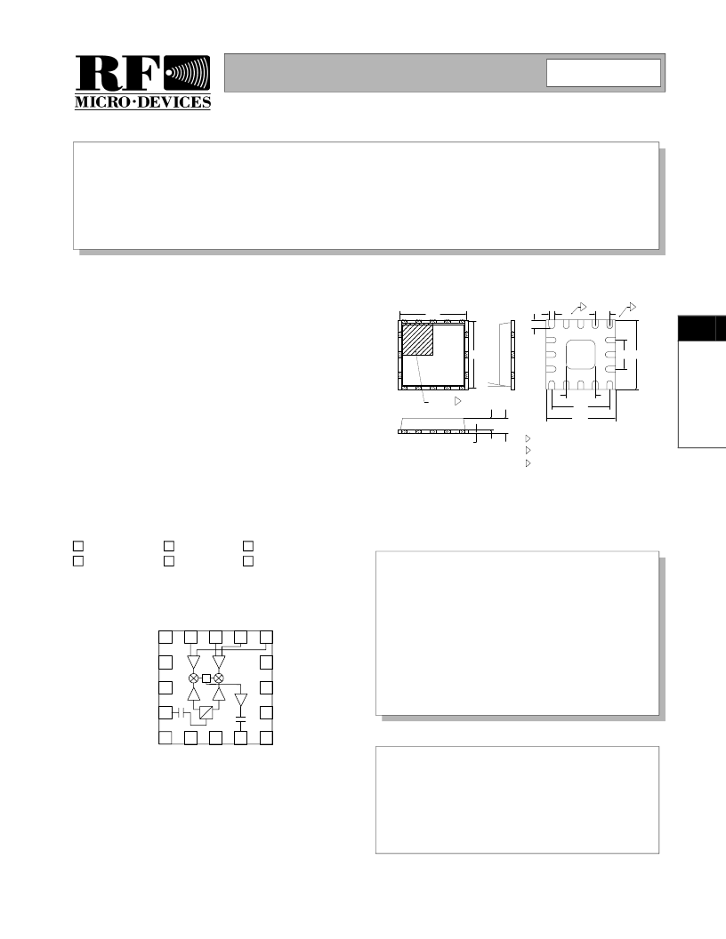
The RF2484 is a monolithic integrated quadrature modu-
lator IC capable of universal direct modulation for high-
frequency AM, PM, or compound carriers. This low-cost
IC features excellent linearity, noise floor, and over-tem-
perature carrier suppression performance.
implements differential amplifiers for the modulation
inputs, 90° carrier phase shift network, carrier limiting
amplifiers, two matched double-balanced mixers, sum-
ming amplifier, and an output RF amplifier which will drive
50
from 800MHz to 2500MHz. It is packaged in a small
industry-standard LCC 16-pin plastic package.
The device
Typical Carrier Suppression>35dBc,
Sideband Suppression>35dBc over
temperature with highly linear operation
Noise Floor better than -152dBm/Hz
from 800MHz to 2200MHz
Single 5V Power Supply
RF2484
RF2484 PCBA
Direct Quadrature Modulator
Fully Assembled Evaluation Board
5
Rev A2 010829
3.75
3.75
+
1.50 SQ
4.00
4.00
1
0.45
0.28
3.20
1.60
0.75
0.50
12°
INDEX AREA3
1.00
0.90
0.75
0.65
0.05
0.00
NOTES:
5
Package Warpage: 0.05 max.
4
Pins 1 and 9 are fused.
Shaded Pin is Lead 1.
1
Dimension applies to plated terminal and is measured between
0.10 mm and 0.25 mm from terminal tip.
2
The terminal #1 identifier and terminal numbering convention
shall conform to JESD 95-1 SPP-012. Details of terminal #1
identifier are optional, but must be located within the zone
indicated. The identifier may be either a mold or marked
feature.
3
0.80
TYP
2
1
Dimensions in mm.
Package S tyle: LCC , 16-Pin
相關(guān)PDF資料 |
PDF描述 |
|---|---|
| RF2485 | VHF QUADRATURE MODULATOR |
| RF2486 | PCS LOW NOISE AMPLIFIER/MIXER |
| RF2488 | MULTI-MODE DUAL-BAND LNA MIXER |
| RF2489 | DUAL-BAND/TRI-MODE CDMA LOW NOISE AMPLIFIER/MIXER |
| RF2492 | DUAL-BAND LOW NOISE AMPLIFIER/MIXER |
相關(guān)代理商/技術(shù)參數(shù) |
參數(shù)描述 |
|---|---|
| RF2484_06 | 制造商:RFMD 制造商全稱:RF Micro Devices 功能描述:DIRECT QUADRATURE MODULATOR |
| RF2484_1 | 制造商:RFMD 制造商全稱:RF Micro Devices 功能描述:DIRECT QUADRATURE MODULATOR |
| RF2484PCBA-410 | 制造商:RFMD 制造商全稱:RF Micro Devices 功能描述:DIRECT QUADRATURE MODULATOR |
| RF2484PCK | 制造商:RF Micro Devices Inc 功能描述:KIT EVAL FOR RF2484 |
| RF2484TR7 | 制造商:RF Micro Devices Inc 功能描述:IC QUADRATURE MOD DUAL-BND 16QFN |
發(fā)布緊急采購,3分鐘左右您將得到回復。