- 您現(xiàn)在的位置:買賣IC網(wǎng) > Datasheet目錄56 > RE46C180S16TF (Microchip Technology)IC ION SMOKE DETECT ASIC 16SOIC Datasheet資料下載
參數(shù)資料
| 型號: | RE46C180S16TF |
| 廠商: | Microchip Technology |
| 文件頁數(shù): | 19/58頁 |
| 文件大?。?/td> | 851K |
| 描述: | IC ION SMOKE DETECT ASIC 16SOIC |
| 標準包裝: | 2,600 |
| 系列: | * |
第1頁第2頁第3頁第4頁第5頁第6頁第7頁第8頁第9頁第10頁第11頁第12頁第13頁第14頁第15頁第16頁第17頁第18頁當前第19頁第20頁第21頁第22頁第23頁第24頁第25頁第26頁第27頁第28頁第29頁第30頁第31頁第32頁第33頁第34頁第35頁第36頁第37頁第38頁第39頁第40頁第41頁第42頁第43頁第44頁第45頁第46頁第47頁第48頁第49頁第50頁第51頁第52頁第53頁第54頁第55頁第56頁第57頁第58頁

?2011 Microchip Technology Inc.
DS22275A-page 19
RE46C180
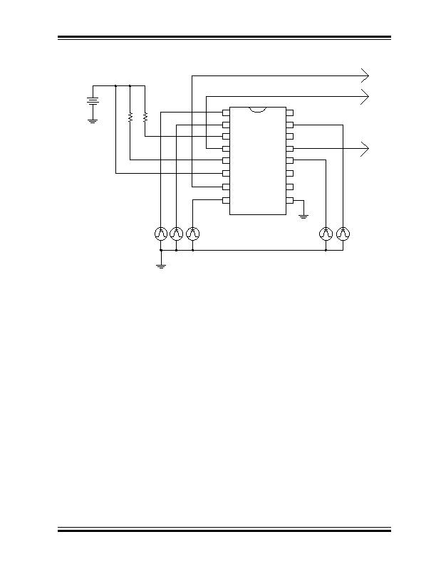
FIGURE 4-1:
Nominal Application Circuit for Programming.
4.2
Smoke Calibration
A separate calibration mode is entered for each mea-
surement mode (Normal, Hysteresis, HUSH and
PTT/Chamber Test) so that independent limits can be
set for each.
In all calibration modes the V
SEN
voltage, which repre-
sents the smoke sensitivity level, can be accessed at
T3 output. The SmkCompOut output voltage is the
result of the comparison of DETECT and V
SEN
, and
can be accessed at TESTOUT output. The FEED input
can be clocked to cycle through the available smoke
sensitivity levels. Once the desired smoke sensitivity
level is reached, the IO input is pulsed low to high to
store the result.
The detailed procedure is described in the following
steps:
1. Power up with the bias condition shown in
Figure 4-1. At power-up:
TEST = IO = FEED = T2 = V
SS
,
DETECT = V
DD
. Now in mode M0.
2. Drive T2 input from V
SS
to V
DD
and hold at V
DD
to enter TM0.
3. Drive TEST from V
SS
to V
DD
and hold at V
DD
.
4. Apply four clock pulses to the T2 input (V
DD
to
V
SS
and back to V
DD
) to enter in TM4 mode.
This initiates the Calibration mode for the normal
sensitivity setting. Drive TEST from V
DD
to V
SS
to turn on the smoke comparator and enable the
T3 switch. The standby smoke sensitivity V
SEN
will appear at T3. The smoke comparator output
will appear at TESTOUT. Clock FEED to
increase or decrease the V
SEN
levels as
needed. The IO input is pulsed low-to-high to
save the result.
5. Drive TEST from V
SS
to V
DD
and hold at V
DD
.
Apply another clock pulse to the T2 input, to
enter in TM5 mode. This initiates the Calibration
mode for the hysteresis setting. Drive TEST
from V
DD
to V
SS
to turn on the smoke compara-
tor and enable the T3 switch. The local alarm
smoke sensitivity V
SEN
will appear at T3. The
smoke comparator output will appear at TES-
TOUT. Clock FEED to increase or decrease the
V
SEN
levels as needed. The IO input is pulsed
low-to-high to save the result.
V
Battery
+
-
R1
1
k
TEST
IO
GLED
CHAMBER
RLED
DD
TESTOUT
FEED
GUARD2
DETECT
T3
T2
HS
HB
VSS
1
2
3
4
5
6
7
8
9
10
11
12
13
14
15
16
RE46C180
R2
1
k
V1
V2 V3 V4
V5
V6
Monitor TESTOUT,
T3 and CHAMBER
GUARD1
V
相關PDF資料 |
PDF描述 |
|---|---|
| RFPIC12F675KT-I/SS | IC MCU 1KX14 RF FSK/ASK 20SSOP |
| RPM841-H11E2A | MODULE IRDA 115.2KBPS 7-SMD |
| RPM841-H16E4A1 | MODULE IRDA 115.2KBPS 7-SMD |
| RPM870-H14E2 | MODULE IRDA 115.2KBPS 8SMD |
| RPM871-E2 | MODULE IRDA 115.2KBPS 8SMD |
相關代理商/技術參數(shù) |
參數(shù)描述 |
|---|---|
| RE46C190 | 制造商:MICROCHIP 制造商全稱:Microchip Technology 功能描述:CMOS Low Voltage Photoelectric Smoke Detector ASIC with Interconnect |
| RE46C190S16F | 功能描述:煙霧報警器 3V E-Cal Photo S.D. IC RoHS:否 制造商:ELMOS Semiconductor 描述/功能:Smoke detector controller 感應方式:Photoelectric 工作電源電壓:24 V 輸出信號類型: |
| RE46C190S16F | 制造商:Microchip Technology Inc 功能描述:3V E-Cal Photo S.D. IC 16 SOIC .150in TU 制造商:Microchip Technology Inc 功能描述:IC, CMOS SMOKE DETECTOR, 5V, 1UA, SOIC-16 |
| RE46C190S16TF | 功能描述:煙霧報警器 3V E-Cal Photo S.D. IC RoHS:否 制造商:ELMOS Semiconductor 描述/功能:Smoke detector controller 感應方式:Photoelectric 工作電源電壓:24 V 輸出信號類型: |
| RE46C311 | 制造商:MICROCHIP 制造商全稱:Microchip Technology 功能描述:Low-Input Leakage, Rail-to-Rail Input/Output Op Amps |
發(fā)布緊急采購,3分鐘左右您將得到回復。