- 您現(xiàn)在的位置:買賣IC網(wǎng) > PDF目錄368408 > PZT751T3 TRANSISTOR | BJT | PNP | 60V V(BR)CEO | 2A I(C) | TO-261AA PDF資料下載
參數(shù)資料
| 型號: | PZT751T3 |
| 英文描述: | TRANSISTOR | BJT | PNP | 60V V(BR)CEO | 2A I(C) | TO-261AA |
| 中文描述: | 晶體管|晶體管|進步黨| 60V的五(巴西)總裁|甲一(c)|至261AA |
| 文件頁數(shù): | 5/8頁 |
| 文件大小: | 54K |
| 代理商: | PZT751T3 |
PZT751T1
http://onsemi.com
5
TYPICAL SOLDER HEATING PROFILE
For any given circuit board, there will be a group of
control settings that will give the desired heat pattern. The
operator must set temperatures for several heating zones,
and a figure for belt speed. Taken together, these control
settings make up a heating “profile” for that particular
circuit board. On machines controlled by a computer, the
computer remembers these profiles from one operating
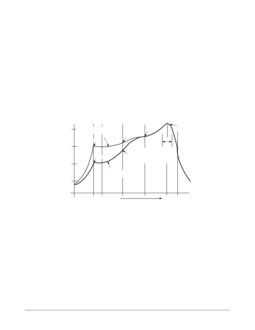
session to the next. Figure 2 shows a typical heating profile
for use when soldering a surface mount device to a printed
circuit board. This profile will vary among soldering
systems but it is a good starting point. Factors that can affect
the profile include the type of soldering system in use,
density and types of components on the board, type of solder
used, and the type of board or substrate material being used.
This profile shows temperature versus time. The line on the
graph shows the actual temperature that might be
experienced on the surface of a test board at or near a central
solder joint. The two profiles are based on a high density and
a
low
density
board.
convection/infrared reflow soldering system was used to
generate this profile. The type of solder used was 62/36/2
Tin Lead Silver with a melting point between 177–189
°
C.
When this type of furnace is used for solder reflow work, the
circuit boards and solder joints tend to heat first. The
components on the board are then heated by conduction. The
circuit board, because it has a large surface area, absorbs the
thermal energy more efficiently, then distributes this energy
to the components. Because of this effect, the main body of
a component may be up to 30 degrees cooler than the
adjacent solder joints.
The
Vitronics
SMD310
STEP 1
PREHEAT
ZONE 1
RAMP"
STEP 2
VENT
SOAK"
STEP 3
HEATING
ZONES 2 & 5
RAMP"
STEP 4
HEATING
ZONES 3 & 6
SOAK"
STEP 5
HEATING
ZONES 4 & 7
SPIKE"
170
°
C
STEP 6
VENT
STEP 7
COOLING
200
°
C
150
°
C
100
°
C
50
°
C
TIME (3 TO 7 MINUTES TOTAL)
Figure 2. Typical Solder Heating Profile
T
MAX
SOLDER IS LIQUID FOR
40 TO 80 SECONDS
(DEPENDING ON
MASS OF ASSEMBLY)
205
°
TO
219
°
C
PEAK AT
SOLDER
JOINT
DESIRED CURVE FOR LOW
MASS ASSEMBLIES
DESIRED CURVE FOR HIGH
MASS ASSEMBLIES
100
°
C
150
°
C
160
°
C
140
°
C
相關PDF資料 |
PDF描述 |
|---|---|
| PZTA05 | TRANSISTOR | BJT | NPN | 60V V(BR)CEO | 500MA I(C) | SOT-223 |
| PZTA42 | NPN High Voltage Amplifier(NPN高電壓放大器) |
| PZTA55 | PNP General Purpose Amplifier |
| PZTA56 | PNP General Purpose Amplifier |
| PZTA56 | PNP general purpose transistor |
相關代理商/技術參數(shù) |
參數(shù)描述 |
|---|---|
| PZT772 | 制造商:SECOS 制造商全稱:SeCoS Halbleitertechnologie GmbH 功能描述:Epitaxial Planar Transistor |
| PZT882 | 制造商:SECOS 制造商全稱:SeCoS Halbleitertechnologie GmbH 功能描述:Epitaxial Planar Transistor |
| PZT949 | 制造商:SECOS 制造商全稱:SeCoS Halbleitertechnologie GmbH 功能描述:Silicon Planar High Current Gain Transistor |
| PZT951 | 制造商:WEITRON 制造商全稱:Weitron Technology 功能描述:PNP Silicon Planar High Current Transistor |
| PZT965 | 制造商:SECOS 制造商全稱:SeCoS Halbleitertechnologie GmbH 功能描述:Epitaxial Planar Transistor |
發(fā)布緊急采購,3分鐘左右您將得到回復。