- 您現(xiàn)在的位置:買賣IC網(wǎng) > PDF目錄368391 > PXAS37KFA512 IC-SM-16-BIT MCU PDF資料下載
參數(shù)資料
| 型號(hào): | PXAS37KFA512 |
| 英文描述: | IC-SM-16-BIT MCU |
| 中文描述: | 集成電路釤16位MCU |
| 文件頁數(shù): | 22/51頁 |
| 文件大?。?/td> | 405K |
| 代理商: | PXAS37KFA512 |
第1頁第2頁第3頁第4頁第5頁第6頁第7頁第8頁第9頁第10頁第11頁第12頁第13頁第14頁第15頁第16頁第17頁第18頁第19頁第20頁第21頁當(dāng)前第22頁第23頁第24頁第25頁第26頁第27頁第28頁第29頁第30頁第31頁第32頁第33頁第34頁第35頁第36頁第37頁第38頁第39頁第40頁第41頁第42頁第43頁第44頁第45頁第46頁第47頁第48頁第49頁第50頁第51頁
Philips Semiconductors
XA 16-bit microcontroller
32K/1K OTP/ROM/ROMless, 8-channel 8-bit A/D, low voltage (2.7 V–5.5 V),
I
2
C, 2 UARTs, 16 MB address range
Preliminary specification
XA-S3
2000 Mar 09
22
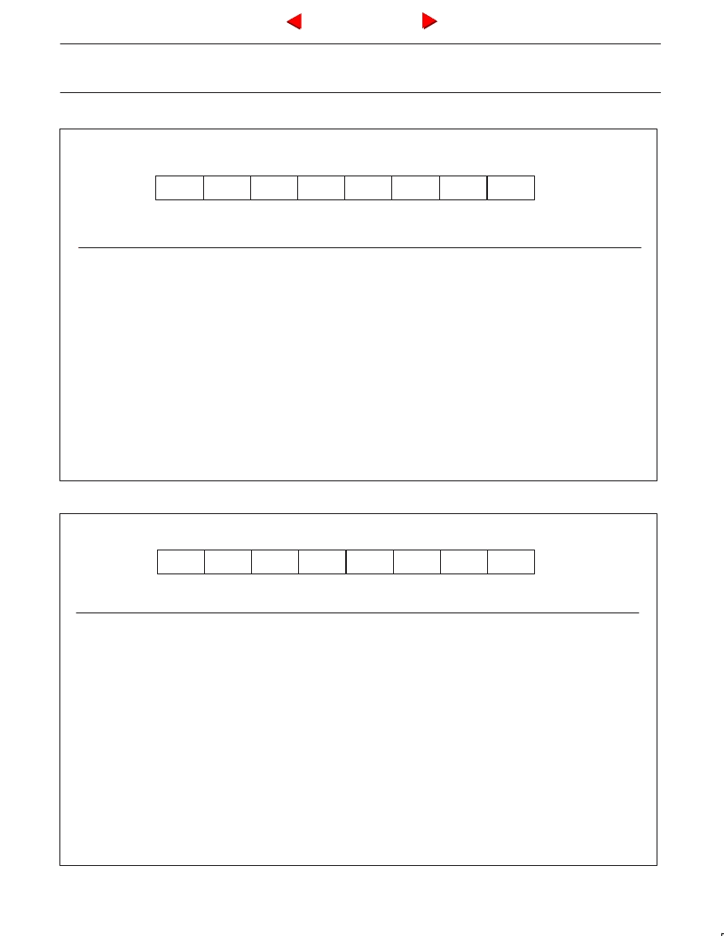
CMOD
Address = 490H
Reset Value = 00H
CIDL
WDTE
–
–
–
CPS1
CPS0
ECF
Bit:
Symbol
Function
CIDL
Counter Idle control: CIDL = 0 programs the PCA Counter to continue functioning during idle Mode. CIDL = 1 programs
it to be gated off during idle.
Watchdog Timer Enable: WDTE = 0 disables Watchdog Timer function on PCA Module 4. WDTE = 1 enables it.
Not implemented, reserved for future use.*
PCA Count Pulse Select bit 1.
PCA Count Pulse Select bit 0.
WDTE
–
CPS1
CPS0
CPS1
0
1
1
PCA Enable Counter Overflow interrupt: ECF = 1 enables CF bit in CCON to generate an interrupt. ECF = 0 disables
that function of CF.
CPS0
X
0
1
PCA Timer Count Source
TClk (Osc/4, Osc/16, or Osc/64)
Timer 0 overflow
ECI (PCA External Clock Input (max rate = Osc/4)
ECF
NOTE:
*
User software should not write 1s to reserved bits. These bits may be used in future products to invoke new features. In that case, the reset or inactive value of the new bit will be
0, and its active value will be 1. The value read from a reserved bit is indeterminate.
** f
OSC
= oscillator frequency
SU01306
7
6
5
4
3
2
1
0
Figure 10. CMOD: PCA Counter Mode Register
CCON
Address = 41AH
Bit Addressable
Reset Value = 00H
CF
CR
–
CCF4
CCF3
CCF2
CCF1
CCF0
Bit:
Symbol
Function
CF
PCA Counter Overflow flag. Set by hardware when the counter rolls over. CF flags an interrupt if bit ECF in CMOD is
set. CF may be set by either hardware or software but can only be cleared by software.
PCA Counter Run control bit. Set by software to turn the PCA counter on. Must be cleared by software to turn the PCA
counter off.
Not implemented, reserved for future use*.
PCA Module 4 interrupt flag. Set by hardware when a match or capture occurs. Must be cleared by software.
May generate a separate interrupt for this module alone.
PCA Module 3 interrupt flag. Set by hardware when a match or capture occurs. Must be cleared by software.
May generate a separate interrupt for this module alone.
PCA Module 2 interrupt flag. Set by hardware when a match or capture occurs. Must be cleared by software.
May generate a separate interrupt for this module alone.
PCA Module 1 interrupt flag. Set by hardware when a match or capture occurs. Must be cleared by software.
May generate a separate interrupt for this module alone.
PCA Module 0 interrupt flag. Set by hardware when a match or capture occurs. Must be cleared by software.
May generate a separate interrupt for this module alone.
CR
–
CCF4
CCF3
CCF2
CCF1
CCF0
Each of CCF4 through CCF0 generates its own interrupt, and has its own interrupt vector.
NOTE:
*
User software should not write 1s to reserved bits. These bits may be used in future products to invoke new features. In that case, the reset or inactive value of the new bit will be
0, and its active value will be 1. The value read from a reserved bit is indeterminate.
SU01307
7
6
5
4
3
2
1
0
Figure 11. CCON: PCA Counter Control Register
Next
Back
相關(guān)PDF資料 |
PDF描述 |
|---|---|
| PXAS30KBA512 | IC-SM-16-BIT MCU |
| PXAS30KFA512 | IC-SM-16-BIT MCU |
| PXAS37KBA512 | IC-SM-16-BIT MCU |
| PXAS83XFA | XA 16-bit microcontroller(XA 16位微控制器) |
| PXAS31KFA | XA 16-bit microcontroller 32K/1K OTP/ROM/ROMless, 8-channel 8-bit A/D, low voltage 2.7 V.5.5 V, I2C, 2 UARTs, 16MB address range |
相關(guān)代理商/技術(shù)參數(shù) |
參數(shù)描述 |
|---|---|
| PXAS37KFBE | 制造商:PHILIPS 制造商全稱:NXP Semiconductors 功能描述:XA 16-bit microcontroller 32 K/1 K OTP/ROM/ROMless, 8-channel 8-bit A/D, low voltage 2.7 V.5.5 V, I2C, 2 UARTs, 16 MB address range |
| PXAS83XFA | 制造商:PHILIPS 制造商全稱:NXP Semiconductors 功能描述:XA 16-bit microcontroller 32K/1K OTP/ROM/ROMless, 8-channel 8-bit A/D, low voltage 2.7 V.5.5 V, I2C, 2 UARTs, 16MB address range |
| PXAS83XFBE | 制造商:PHILIPS 制造商全稱:NXP Semiconductors 功能描述:XA 16-bit microcontroller 32K/1K OTP/ROM/ROMless, 8-channel 8-bit A/D, low voltage 2.7 V.5.5 V, I2C, 2 UARTs, 16MB address range |
| PXASCCKFBE | 制造商:PHILIPS 制造商全稱:NXP Semiconductors 功能描述:CMOS 16-bit communications microcontroller |
| PXB 4210 EL V1.2-G | 制造商:Lantiq 功能描述:LTQPXB 4210 EL V1.2-G LQ000001141_GRX288 |
發(fā)布緊急采購,3分鐘左右您將得到回復(fù)。