- 您現(xiàn)在的位置:買賣IC網(wǎng) > PDF目錄368095 > PPC405EP-3GB266C (APPLIEDMICRO INC) PowerPC 405EP Embedded Processor PDF資料下載
參數(shù)資料
| 型號(hào): | PPC405EP-3GB266C |
| 廠商: | APPLIEDMICRO INC |
| 元件分類: | 微控制器/微處理器 |
| 英文描述: | PowerPC 405EP Embedded Processor |
| 中文描述: | 32-BIT, 266.66 MHz, RISC PROCESSOR, PBGA385 |
| 封裝: | 31 X 31 MM, PLASTIC, EBGA-385 |
| 文件頁數(shù): | 32/50頁 |
| 文件大小: | 373K |
| 代理商: | PPC405EP-3GB266C |
第1頁第2頁第3頁第4頁第5頁第6頁第7頁第8頁第9頁第10頁第11頁第12頁第13頁第14頁第15頁第16頁第17頁第18頁第19頁第20頁第21頁第22頁第23頁第24頁第25頁第26頁第27頁第28頁第29頁第30頁第31頁當(dāng)前第32頁第33頁第34頁第35頁第36頁第37頁第38頁第39頁第40頁第41頁第42頁第43頁第44頁第45頁第46頁第47頁第48頁第49頁第50頁
PPC405EP – PowerPC 405EP Embedded Processor
32
AMCC
Revision 1.07 – September 10, 2007
Data Sheet
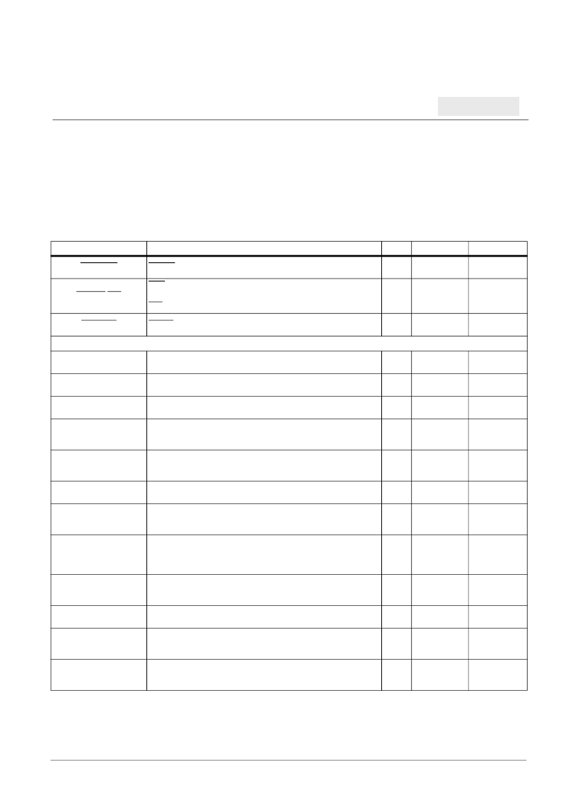
PCIReq1:2
PCIReq input when internal arbiter is used.
I
5V tolerant
3.3V PCI
PCIGnt0/Req
Gnt0 when internal arbiter is used
or
Req when external arbiter is used.
O
5V tolerant
3.3V PCI
PCIGnt1:2
PCIGnt output when internal arbiter is used.
O
5V tolerant
3.3V PCI
Ethernet Interface
PHY0Rx0:1D3:0
Received data. This is a nibble wide bus from the PHY. The data is
synchronous with the PHY0RxClk.
I
5V tolerant
3.3V LVTTL
1
EMC0Tx0:1D3:0
Transmit data. A nibble wide data bus towards the net. The data is
synchronous to the PHY0TxClk.
O
5V tolerant
3.3V LVTTL
PHY0Rx0:1Err
Receive Error. This signal comes from the PHY and is synchronous to
the PHY0RxClk.
I
5V tolerant
3.3V LVTTL
1
PHY0Rx0:1Clk
Receive Medium clock. This signal is generated by the PHY. If an
EMAC interface is not used, this clock must be present in order to
reset the EMAC.
I
5V tolerant
3.3V LVTTL
1
PHY0Rx0:1DV
Receive Data Valid. Data on the Data Bus is valid when this signal is
activated. Deassertion of this signal indicates end of the frame
reception.
I
5V tolerant
3.3V LVTTL
1
PHY0CrS0:1
Carrier Sense signal from the PHY. This is an asynchronous signal.
I
5V tolerant
3.3V LVTTL
1
EMC0Tx0:1Err
Transmit Error. This signal is generated by the Ethernet controller, is
connected to the PHY and is synchronous with the PHYTxClk. It
informs the PHY that an error was detected.
O
5V tolerant
3.3V LVTTL
EMC0Tx0:1En
Transmit Enable. This signal is driven by the EMAC to the PHY. Data
is valid during the active state of this signal. Deassertion of this signal
indicates end of frame transmission. This signal is synchronous to the
PHY0TxClk.
O
5V tolerant
3.3V LVTTL
PHY0Tx0:1Clk
This clock comes from the PHY and is the Medium Transmit clock. If
an EMAC interface is not used, this clock must be present in order to
reset the EMAC.
I
5V tolerant
3.3V LVTTL
1
PHY0Col0:1
Collision signal from the PHY. This is an asynchronous signal.
I
5V tolerant
3.3V LVTTL
1
EMC0MDClk
Management Data Clock. The MDClk is sourced to the PHY.
Management information is transferred synchronously with respect to
this clock.
O
5V tolerant
3.3V LVTTL
EMC0MDIO
Management Data Input/Output is a bidirectional signal between the
Ethernet controller and the PHY. It is used to transfer control and
status information.
I/O
5V tolerant
3.3V LVTTL
1
Table 6. Signal Functional Description (Sheet 2 of 6)
Secondary multiplexed signals are shown in brackets.
Notes:
1. Receiver input has hysteresis.
2. Must pull up. See “Pull-Up and Pull-Down Resistors” on page 29 for recommended termination values.
3. Must pull down. See “Pull-Up and Pull-Down Resistors” on page 29 for recommended termination values.
4. If not used, must pull up.
5. If not used, must pull down.
6. Strapping input during reset; pull up or pull down as required.
7. Pull-up may be required. See “External Bus Control Signals” on page 30.
Signal Name
Description
I/O
Type
Notes
相關(guān)PDF資料 |
PDF描述 |
|---|---|
| PPC405EP-3GB266CZ | PowerPC 405EP Embedded Processor |
| PPC405EP-3GB333C | PowerPC 405EP Embedded Processor |
| PPC405EP-3GB333CZ | PowerPC 405EP Embedded Processor |
| PPC405EP-3LB133C | PowerPC 405EP Embedded Processor |
| PPC405EP-3LB133CZ | PowerPC 405EP Embedded Processor |
相關(guān)代理商/技術(shù)參數(shù) |
參數(shù)描述 |
|---|---|
| PPC405EP-3GB266CZ | 制造商:AppliedMicro 功能描述:MPU 405EP RISC 32-Bit 0.18um 266MHz 3.3V 385-Pin EBGA T/R |
| PPC405EP-3GB333C | 制造商:AppliedMicro 功能描述:MPU 405EP RISC 32-Bit 0.18um 333MHz 3.3V 385-Pin EBGA Tray 制造商:AMCC 功能描述:MPU 405EP RISC 32BIT 0.18UM 333MHZ 3.3V 385PIN EBGA - Trays |
| PPC405EP-3GB333CZ | 制造商:AppliedMicro 功能描述:MPU 405EP RISC 32-Bit 0.18um 333MHz 3.3V 385-Pin EBGA T/R |
| PPC405EP-3LB133C | 制造商:AppliedMicro 功能描述:MPU 405EP RISC 32-Bit 0.18um 133MHz 3.3V 385-Pin EBGA Tray 制造商:AMCC 功能描述:MPU 405EP RISC 32BIT 0.18UM 133MHZ 3.3V 385PIN EBGA - Trays 制造商:AMCC 功能描述:AMCPPC405EP-3LB133C 32 Bit PowerPC |
| PPC405EP-3LB133CZ | 制造商:AppliedMicro 功能描述:MPU 405EP RISC 32-Bit 0.18um 133MHz 3.3V 385-Pin EBGA T/R |
發(fā)布緊急采購(gòu),3分鐘左右您將得到回復(fù)。