- 您現(xiàn)在的位置:買(mǎi)賣(mài)IC網(wǎng) > PDF目錄378055 > PM5945-UTP5 (PMC-Sierra, Inc.) ATM PHYSICAL INTERFACE APPLICATION BOARD FOR CAT-5 UTP PDF資料下載
參數(shù)資料
| 型號(hào): | PM5945-UTP5 |
| 廠商: | PMC-Sierra, Inc. |
| 英文描述: | ATM PHYSICAL INTERFACE APPLICATION BOARD FOR CAT-5 UTP |
| 中文描述: | ATM物理接口貓應(yīng)用板- 5雙絞線 |
| 文件頁(yè)數(shù): | 63/84頁(yè) |
| 文件大小: | 1666K |
| 代理商: | PM5945-UTP5 |
第1頁(yè)第2頁(yè)第3頁(yè)第4頁(yè)第5頁(yè)第6頁(yè)第7頁(yè)第8頁(yè)第9頁(yè)第10頁(yè)第11頁(yè)第12頁(yè)第13頁(yè)第14頁(yè)第15頁(yè)第16頁(yè)第17頁(yè)第18頁(yè)第19頁(yè)第20頁(yè)第21頁(yè)第22頁(yè)第23頁(yè)第24頁(yè)第25頁(yè)第26頁(yè)第27頁(yè)第28頁(yè)第29頁(yè)第30頁(yè)第31頁(yè)第32頁(yè)第33頁(yè)第34頁(yè)第35頁(yè)第36頁(yè)第37頁(yè)第38頁(yè)第39頁(yè)第40頁(yè)第41頁(yè)第42頁(yè)第43頁(yè)第44頁(yè)第45頁(yè)第46頁(yè)第47頁(yè)第48頁(yè)第49頁(yè)第50頁(yè)第51頁(yè)第52頁(yè)第53頁(yè)第54頁(yè)第55頁(yè)第56頁(yè)第57頁(yè)第58頁(yè)第59頁(yè)第60頁(yè)第61頁(yè)第62頁(yè)當(dāng)前第63頁(yè)第64頁(yè)第65頁(yè)第66頁(yè)第67頁(yè)第68頁(yè)第69頁(yè)第70頁(yè)第71頁(yè)第72頁(yè)第73頁(yè)第74頁(yè)第75頁(yè)第76頁(yè)第77頁(yè)第78頁(yè)第79頁(yè)第80頁(yè)第81頁(yè)第82頁(yè)第83頁(yè)第84頁(yè)
S
TANDARD
P
RODUCT
PMC-Sierra, Inc.
PM5945 -UTP5
PMC-940202 ISSUE 2. APRIL 7, 1995
______________________________________________________________________________________________
APP_SAPI_UTP5
______________________________________________________________________________________________
54
Z
o
=
87
ε
r
+1.41
×
ln
5.98
×
h
0.8
×
w+ t
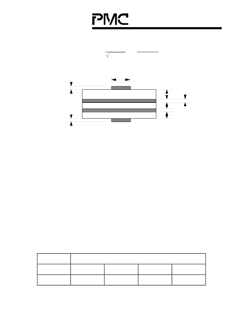
and based on the following layer setup:
dielectric
dielectric
dielectric
1 Oz Copper
1 Oz Copper
1 Oz Copper
t
t
h
1
h
2
h
3
t
Ground Plane
Power Plane
w
ε
r
ε
r
ε
r
where
ε
r
= relative dielectric constant, nominally 5.0 for G-10 fibre-glass epoxy
t = thickness of the copper, fixed according to the weight of copper selected.
For 1 oz copper, the thickness is 1.4 mil. This thickness can be ignored
if w is great enough.
h1, h2, h3 = thickness of dielectric.
w = width of copper
The parameters h1, h2, and h3 can be specified. For example, if a 20 mil (including
the copper thickness on both sides of the board) two layer core is selected, dielectric
material that has the same relative dielectric constant can be added to the both
sides of the core to construct a 4 layer board.
Since all the controlled impedance traces are on the component side, only h1 is
relevant in calculating the trace width. The calculation for the reference design is
shown in the table below:
Note: The relative dielectric constant is specified to be between 4.8 and 5.4.
Parameter
Data
ε
r
4.8
5.4
4.8
5.4
h (mil)
62
62
62
62
相關(guān)PDF資料 |
PDF描述 |
|---|---|
| PM5945 | CONN |
| PM6341 | E1 TRANSCEIVER |
| PM6341-QI | Ultraframer DS3/E3/DS2/E2/DS1/E1/DS0 |
| PM6341-RI | Ultraframer DS3/E3/DS2/E2/DS1/E1/DS0 |
| PM6344-RI | KPSE SERIES |
相關(guān)代理商/技術(shù)參數(shù) |
參數(shù)描述 |
|---|---|
| PM594D | 制造商:未知廠家 制造商全稱:未知廠家 功能描述:Analog IC |
| PM594DS | 制造商:未知廠家 制造商全稱:未知廠家 功能描述:Analog IC |
| PM594K | 制造商:未知廠家 制造商全稱:未知廠家 功能描述:Analog IC |
| PM594KS | 制造商:未知廠家 制造商全稱:未知廠家 功能描述:Analog IC |
| PM594S | 制造商:未知廠家 制造商全稱:未知廠家 功能描述:Analog IC |
發(fā)布緊急采購(gòu),3分鐘左右您將得到回復(fù)。