- 您現(xiàn)在的位置:買賣IC網(wǎng) > PDF目錄224662 > PAC80 (Lattice Semiconductor Corporation) In-System Programmable Analog Circuit PDF資料下載
參數(shù)資料
| 型號: | PAC80 |
| 廠商: | Lattice Semiconductor Corporation |
| 英文描述: | In-System Programmable Analog Circuit |
| 中文描述: | 在系統(tǒng)可編程模擬電路 |
| 文件頁數(shù): | 13/19頁 |
| 文件大?。?/td> | 342K |
| 代理商: | PAC80 |
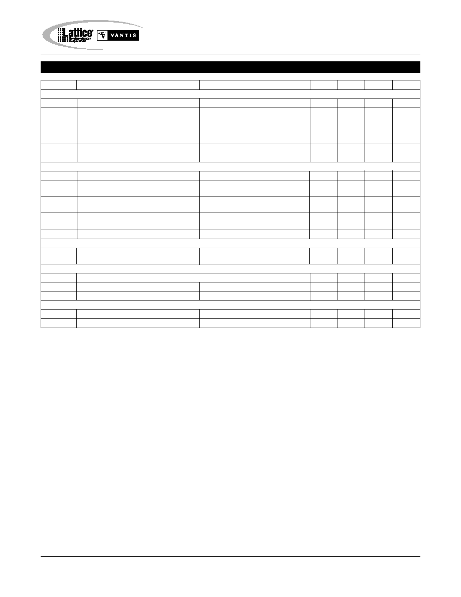
Specifications ispPAC80
3
Symbol
Parameter
Condition
Min.
Typ.
Max.
Units
Dynamic Performance (4)
SNR
Signal to Noise (G=1 to 10)
0.1Hz to 500kHz, FC = 500kHz
83
dB
THD
Total Harmonic Distortion (Differential)
FIN = 10kHz, VIN = 6Vp-p
-90
-74
dB
Single-Ended
FIN = 10kHz, VIN = 6Vp-p
-80
dB
Differential (FP = 500kHz)
FIN = 100kHz, VIN = 6Vp-p
-90
-74
dB
Single-Ended (FP = 500kHz)
FIN = 100kHz, VIN = 6Vp-p
-74
dB
CMR
Common Mode Rejection (VIN = 1V to 4V)
10kHz
60
50
dB
Note: VIN+ and VIN- connected together
100kHz, FC = 500kHz
60
dB
Filter Characteristics (4)
FC
Corner Frequency Programming Range
Elliptic Filter Families
50
500
kHz
|FC|
Absolute Corner Frequency Accuracy
Deviation From Calculated -3dB point
FC = 50, 200 or 500kHZ
0.6
3
%
F
C
Maximum Delta Between Corner
50kHz to 500kHz
3.7
%
Frequencies
F
C/T
Corner Frequency Delta vs. Temperature
FC = 50kHz
0.03
%/
°C
FC = 500kHz
0.05
F
C/V
Corner Frequency Delta vs. Supply Voltage
FC = 50kHz
0.09
%/V
Elliptic Filter Response (5)
Passband Ripple
FC = 50kHz
0.1
dB
FC = 500kHz
0.5
dB
Power Supplies
VS
Operating Supply Voltage
4.75
5
5.25
V
IS
Supply Current
VS = 5.0V
33
40
mA
PD
Power Dissipation
VS = 5.0V
210
mW
Temperature Range
Operation
-40
85
°C
Storage
-65
150
°C
AC Electrical Characteristics
Notes: (1) A wider input range of 0.7V to 4.3V is typical, but not guaranteed. Inputs larger than this will be clipped. Input signals are also subject
to common-mode voltage limitations. Refer to the table of conditions in this datasheet. (2) Refer to theory of operation section later in this datasheet
for explanation of differential voltage swing computation. (3) To insure full spec performance an additional auto-calibration should be performed
after initial turn-on and the device reaches thermal stability. (4) Although many hundreds of thousands of filter configurations are available using
ispPAC80, not every type will have corner frequencies available from exactly 50kHz to 500kHz, depending on the tables available from within PAC-
Designer filter design tools. The general specifications given under this heading are realized using the Elliptic filter types. (5) A Cauer elliptic filter
of type CC051042 (see datasheet text) is used to guarantee these specific filter accuracy specifications. It is assumed that all other configurations
available in PAC-Designer will exhibit equivalent performance according to the applicability of the individual filter type. Necessary limitations will
apply, however, when specifications do not directly apply. See the data sheet text, application notes and guides in PAC-Designer for specific filter
type considerations.
相關(guān)PDF資料 |
PDF描述 |
|---|---|
| PACE1754-20PGMB | SPECIALTY MICROPROCESSOR CIRCUIT, CPGA68 |
| PAL16R8ANC | Progammable Array Logic Series 24 (PAL Series 24) |
| PAL16R8AVC | Progammable Array Logic Series 24 (PAL Series 24) |
| PAL18C1AN | Progammable Array Logic Series 24 (PAL Series 24) |
| PAL18C1ANC | Progammable Array Logic Series 24 (PAL Series 24) |
相關(guān)代理商/技術(shù)參數(shù) |
參數(shù)描述 |
|---|---|
| PAC80/81-EV | 功能描述:可編程邏輯 IC 開發(fā)工具 ispPAC80 & ispPAC81 Eval Brd RoHS:否 制造商:Altera Corporation 產(chǎn)品:Development Kits 類型:FPGA 工具用于評估:5CEFA7F3 接口類型: 工作電源電壓: |
| P-AC-832-2 | 制造商:PSM International 功能描述: |
| P-AC84RZSZ0U | 制造商:Panasonic Industrial Devices 功能描述:AGITATOR SUB:AC84RBZDZ000 |
| P-AC88RYUZV06 | 制造商:Panasonic Industrial Devices 功能描述:BRUSH |
| PAC91 | 功能描述:測試引線 PRINT ADAPTER CABL RoHS:否 制造商:Pomona Electronics 設備類型:Patch Cords 連接器類型:Banana plug (stackable) on both ends 長度:60 in 顏色:Black |
發(fā)布緊急采購,3分鐘左右您將得到回復。