- 您現(xiàn)在的位置:買賣IC網(wǎng) > PDF目錄367723 > P87C550EFAA (NXP SEMICONDUCTORS) AT25F1024 1M BIT SPI FLASH - SO8 PDF資料下載
參數(shù)資料
| 型號: | P87C550EFAA |
| 廠商: | NXP SEMICONDUCTORS |
| 元件分類: | 微控制器/微處理器 |
| 英文描述: | AT25F1024 1M BIT SPI FLASH - SO8 |
| 中文描述: | 8-BIT, OTPROM, 8 MHz, MICROCONTROLLER, PQCC44 |
| 封裝: | PLASTIC, LCC-44 |
| 文件頁數(shù): | 12/28頁 |
| 文件大小: | 190K |
| 代理商: | P87C550EFAA |
第1頁第2頁第3頁第4頁第5頁第6頁第7頁第8頁第9頁第10頁第11頁當(dāng)前第12頁第13頁第14頁第15頁第16頁第17頁第18頁第19頁第20頁第21頁第22頁第23頁第24頁第25頁第26頁第27頁第28頁
Philips Semiconductors
Product specification
80C550/83C550/87C550
80C51 8-bit microcontroller family
4K/128 OTP/ROM/ROMless, 8 channel 8 bit A/D, watchdog timer
1998 May 01
12
Watchdog Function
The watchdog consists of a programmable prescaler and the main
timer. The prescaler derives its clock from the on-chip oscillator. The
prescaler consists of a divide by 12 followed by a 13 stage counter
with taps from stage 6 through stage 13. The tap selection is
programmable. The watchdog main counter is a down counter
clocked (decremented) each time the programmable prescaler
underflows. The watchdog generates an underflow signal (and is
autoloaded) when the watchdog is at count 0 and the clock to
decrement the watchdog occurs. The watchdog is 8 bits long and
the autoload value can range from 0 to FFH. (The autoload value of
0 is permissible since the prescaler is cleared upon autoload).
This leads to the following user design equations. Definitions: t
OSC
is the oscillator period, N is the selected prescaler tap value, W is
the main counter autoload value, t
MIN
is the minimum watchdog
time-out value (when the autoload value is 0), t
MAX
is the maximum
time-out value (when the autoload value is FFH), t
D
is the design
time-out value.
t
MIN
= t
OSC
×
12
×
64
t
MAX
= t
MIN
×
128
×
256
t
D
= t
MIN
×
2
PRESCALER
×
W
(where prescaler = 0, 1, 2, 3, 4, 5, 6, or 7)
Note that the design procedure is anticipated to be as follows. A
t
MAX
will be chosen either from equipment or operation
considerations and will most likely be the next convenient value
higher than t
D
. (If the watchdog were inadvertently to start from FFH,
an overflow would be guaranteed, barring other anomalies, to occur
within t
MAX
). Then the value for the prescaler would be chosen from:
prescaler = log2 (t
MAX
/ (t
OSC
×
12
×
256)) – 6
This then also fixes t
MIN
. An autoload value would then be chosen
from:
W = t
D
/ t
MIN
– 1
The software must be written so that a feed operation takes place
every t
D
seconds from the last feed operation. Some tradeoffs may
need to be made. It is not advisable to include feed operations in
minor loops or in subroutines unless the feed operation is a specific
subroutine.
Interrupts
The 8XC550 interrupt structure is a seven-source, two-priority level
interrupt system similar to that of the standard 80C51
microcontroller. The interrupt sources are listed below in the order of
their internal polling sequence. This is the order in which
simultaneous interrupts of the same priority level would be serviced.
Interrupt Priorities
PRIORITY
SOURCE
VECTOR
ADDRESS
0003H
000BH
0013H
001BH
0023H
002BH
FUNCTION
Highest
INT0
TF0
INT1
TF1
TI & RI
ADCI
External interrupt 0
Counter/timer 0 overflow
External interrupt 1
Counter/timer 1 overflow
Serial port transmit/receive
A/D converter conversion
complete
Watchdog timer overflow
(only when not in
watchdog mode)
Lowest
WDTOF
0033H
Interrupt Control Registers
The standard 80C51 interrupt enable and priority registers have
been modified slightly to take into account the additional interrupt
sources of the 8XC550.
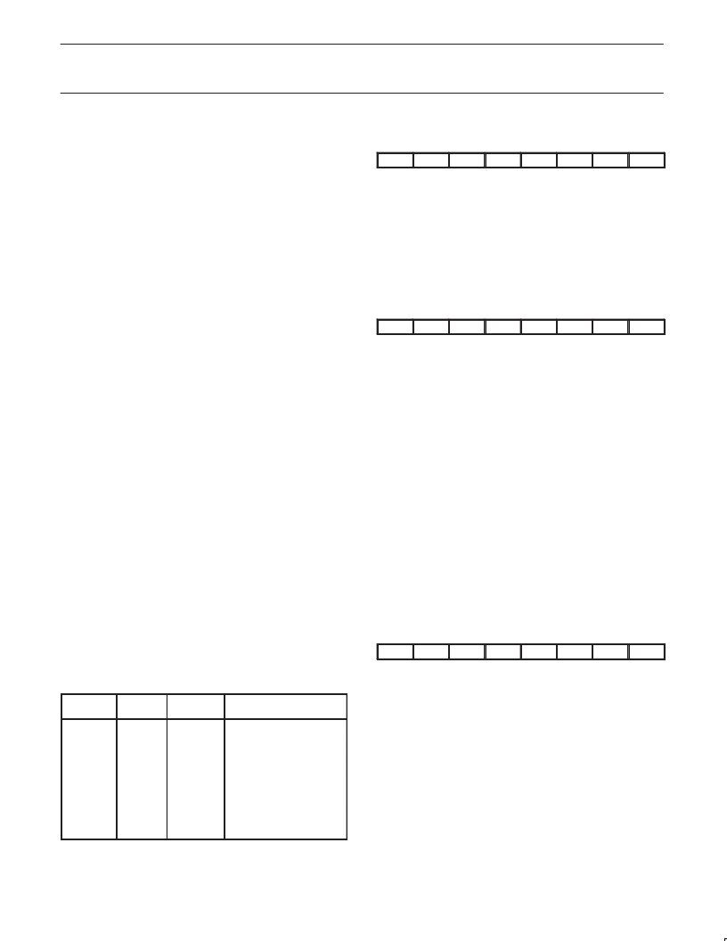
Interrupt Enable Register
MSB
LSB
EA
EWD
EAD
ES
ET1
EX1
ET0
EX0
Symbol Position
EA
EWD
EAD
ES
ET1
EX1
ET0
EX0
Function
IE.7
IE.6
IE.5
IE.4
IE.3
IE.2
IE.1
IE.0
Global interrupt enable
Watchdog timer overflow
A/D conversion complete
Serial port transmit or receive
Timer 1 overflow
External interrupt 1
Timer 0 overflow
External interrupt 0
Interrupt Priority Register
MSB
LSB
–
PWD
PAD
PS
PT1
PX1
PT0
PX0
Symbol Position
PWD
PAD
PS
PT1
PX1
PT0
PX0
Function
IP.6
IP.5
IP.4
IP.3
IP.2
IP.1
IP.0
Watchdog timer
A/D conversion
Serial port interrupt
Timer 1 interrupt
External interrupt 1
Timer 0 interrupt
External interrupt 0
Power-Down and Idle Modes
The 8XC550 includes the standard 80C51 power-down and idle
modes of reduced power consumption. In addition, the 8XC550
includes an option to separately turn off the serial port for extra
power savings when it is not needed. Also, the individual functional
blocks such as the counter/timers are automatically disabled when
they are not running. This actually turns off the clocks to the block in
question, resulting in additional power savings. Note that when the
watchdog timer is operating, the processor is inhibited from entering
the power-down mode. This is due to the fact that the oscillator is
stopped in the power-down mode, which would effectively turn off
the watchdog timer. In keeping with the purpose of the watchdog
timer, the processor is prevented from accidentally entering
power-down due to some erroneous operation.
Power Control Register
MSB
LSB
SMOD
SIDL
–
–
GF1
GF0
PD
IDL
Symbol
SMOD
Position
PCON.7
Function
Double baud rate bit. When set to a 1 and
Timer 1 is used to generate baud rate, and
the serial port is used in modes 1, 2, or 3.
Separately idles the serial port for additional
power savings.
Reserved
Reserved
General-purpose flag bit.
General-purpose flag bit.
Power-down bit. Starting this bit activates
power-down operation.
Idle mode bit. Setting this bit activates
idle mode operation.
SIDL
PCON.6
–
–
GF1
GF0
PD
PCON.5
PCON.4
PCON.3
PCON.2
PCON.1
IDL
PCON.0
If 1s are written to PD and IDL at the same time, PD takes
precedence.
相關(guān)PDF資料 |
PDF描述 |
|---|---|
| P80C557E4EBB | Single-chip 8-bit microcontroller |
| P80C557E8 | 8 BIT MICROCONTROLLER |
| P83C557E8 | 8 BIT MICROCONTROLLER |
| P83C557E4EBB | Single-chip 8-bit microcontroller |
| P83C557E4EFB | Single-chip 8-bit microcontroller |
相關(guān)代理商/技術(shù)參數(shù) |
參數(shù)描述 |
|---|---|
| P87C550EFAA-T | 制造商:未知廠家 制造商全稱:未知廠家 功能描述:8-Bit Microcontroller |
| P87C550EFFA | 制造商:未知廠家 制造商全稱:未知廠家 功能描述:8-Bit Microcontroller |
| P87C550EFK | 制造商:未知廠家 制造商全稱:未知廠家 功能描述:8-Bit Microcontroller |
| P87C550EFKA | 制造商:未知廠家 制造商全稱:未知廠家 功能描述:8-Bit Microcontroller |
| P87C550EFN | 制造商:未知廠家 制造商全稱:未知廠家 功能描述:8-Bit Microcontroller |
發(fā)布緊急采購,3分鐘左右您將得到回復(fù)。