- 您現(xiàn)在的位置:買賣IC網(wǎng) > PDF目錄224604 > NQ60T60EGV05NNS-G (SYNQOR INC) 1-OUTPUT 300 W DC-DC REG PWR SUPPLY MODULE PDF資料下載
參數(shù)資料
| 型號: | NQ60T60EGV05NNS-G |
| 廠商: | SYNQOR INC |
| 元件分類: | 電源模塊 |
| 英文描述: | 1-OUTPUT 300 W DC-DC REG PWR SUPPLY MODULE |
| 封裝: | ROHS COMPLIANT, EIGHTH BRICK PACKAGE-8 |
| 文件頁數(shù): | 3/10頁 |
| 文件大?。?/td> | 1079K |
| 代理商: | NQ60T60EGV05NNS-G |
Product # NQ60x60EGx05
Phone 1-888-567-9596
www.synqor.com
Doc.# 005-0005408 Rev. C
07/14/10
Page 2
Input:
Outputs:
Current:
Package:
9 - 60V
0 - 60V
5.0A
Eighth-brick
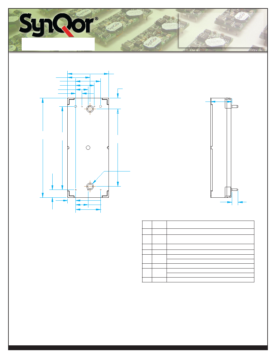
Top View
5
6
7
8
1
2
3
4
Side View
.986±.020 (25.04±0.5)
.263± .020
(25.04±0.5)
0.150 (3.81)
0.450 (11.43)
0.600 (15.24)
0.300 (7.62)
Overall height
0.500 ±0.025
(12
±0.63)
0.145 ± .010
(3.68
±0.25)
.600 (15.24)
.193± .020 (4.9±0.5)
M3 Threaded inserts
2 Places
See Notes 1& 2
.183± .020
(4.65
±0.5)
2.386± .020
(60.6
±0.5)
.300 (7.62)
2.00
(50.8)
1.86
(47.2)
NOTES
1)M3 SCREWS USED TO BOLT UNIT'S BASEPLATE TO OTHER SURFACES
SUCH AS HEATSINKS MUST NOT EXCEED 0.100" (2.54mm) DEPTH
BELOW THE SURFACE OF THE BASEPLATE.
2)APPLIED TORQUE PER SCREW SHOULD NOT EXCEED 6in-lb (0.7Nm)
3)BASEPLATE FLATNESS TOLERANCE IS 0.004" (.10mm)
TIR FOR SURFACE
4)PINS 1-3, 5-7 ARE 0.040" (1.02mm) DIA. WITH 0.080" (2.03mm) DIA.
STANDOFF SHOULDERS
5)PINS 4 AND 8 ARE 0.062" (1.57mm) DIA. WITH 0.100" (2.54mm)
DIA. STANDOFF SHOULDERS
6)ALL PINS: MATERIAL: COPPER ALLOY
FINISH: MATTE TIN OVER NICKEL PLATE
7)UNDIMENSIONED COMPONENTS ARE SHOWN FOR VISUAL
REFERENCE ONLY
8)ALL DIMENSIONS IN INCHES(mm)
TOLERANCES: X.XXIN +/-0.02 (X.Xmm +/-0.5mm)
X.XXXIN +/-0.010 (X.XXmm +/-0.25mm)
9)Weight: 1.7oz (48g) typical
10)Workmanship: Meets or exceeds IPC-A-610 Class II
PINDESIGNATIONS
Pin Label
Function
1
Vin(+)
Positive input
2
ON/OFF
TTL input to turn converter on and off, referenced
to Vin(-), with internal pull up
3
Vin(-)
Negative input voltage, internal short to Pin 4
4
Vout(-)
Negative output voltage, internal short to Pin 3
5
SENSE
(-)
Negative remote sense. See note 1 (S option)
Itrim (C option)
6
TRIM
Output voltage trim
7
SENSE
(+)
Positive remote sense. See note 2 (S option)
Imon (C option)
8
Vout(+)
Positive output voltage
Notes:
1)SENSE(–) should be connected to Vout(–) either remotely or at
the converter
2)SENSE(+) should be connected to Vout(+) either remotely or at
the converter.
Mechanical Diagram
相關(guān)PDF資料 |
PDF描述 |
|---|---|
| NRD104K06 | High-Temperature Durability |
| NRD104K10 | High-Temperature Durability |
| NRD104K16 | High-Temperature Durability |
| NRD104K20 | High-Temperature Durability |
| NRD104K25 | High-Temperature Durability |
相關(guān)代理商/技術(shù)參數(shù) |
參數(shù)描述 |
|---|---|
| NQ60T60ETC10NKC-G | 制造商:SYNQOR 制造商全稱:SYNQOR 功能描述:Eighth-brick DC-DC Converter |
| NQ60T60ETC10NKS-G | 制造商:SYNQOR 制造商全稱:SYNQOR 功能描述:Eighth-brick DC-DC Converter |
| NQ60T60ETC10NNC-G | 制造商:SYNQOR 制造商全稱:SYNQOR 功能描述:Eighth-brick DC-DC Converter |
| NQ60T60ETC10NNS-G | 制造商:SYNQOR 制造商全稱:SYNQOR 功能描述:Eighth-brick DC-DC Converter |
| NQ60T60ETC10NRC-G | 制造商:SYNQOR 制造商全稱:SYNQOR 功能描述:Eighth-brick DC-DC Converter |
發(fā)布緊急采購,3分鐘左右您將得到回復(fù)。