- 您現(xiàn)在的位置:買賣IC網(wǎng) > PDF目錄376214 > MXD6125Q (Electronic Theatre Controls, Inc.) Ultra High Performance 【1g Dual Axis Accelerometer with Digital Outputs PDF資料下載
參數(shù)資料
| 型號(hào): | MXD6125Q |
| 廠商: | Electronic Theatre Controls, Inc. |
| 英文描述: | Ultra High Performance 【1g Dual Axis Accelerometer with Digital Outputs |
| 中文描述: | 超高性能【1克雙軸加速度計(jì)的數(shù)字輸出 |
| 文件頁(yè)數(shù): | 4/6頁(yè) |
| 文件大小: | 104K |
| 代理商: | MXD6125Q |
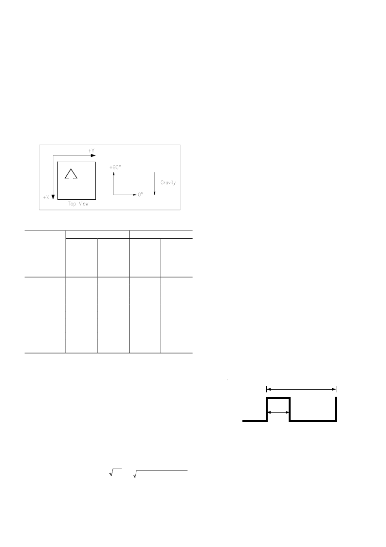
Table 1 and Figure 2 help illustrate the output changes in
the X- and Y-axes as the unit is tilted from +90
°
to 0
°
.
Notice that when one axis has a small change in output per
degree of tilt (in m
g
), the second axis has a large change in
output per degree of tilt. The complementary nature of
these two signals permits low cost accurate tilt sensing to
be achieved with the MEMSIC device (reference
application note AN-00MX-007).
MEMSIC MXD6125Q
Page 4 of 6
2/24/2005
M
Figure 2: Accelerometer Position Relative to Gravity
X-Axis
X-Axis
Orientation
To Earth’s
Surface
(deg.)
90
1.000
85
0.996
80
0.985
70
0.940
60
0.866
45
0.707
30
0.500
20
0.342
10
0.174
5
0.087
0
0.000
Table 1: Changes in Tilt for X- and Y-Axes
Resolution
: The accelerometer resolution is limited by
noise. The output noise will vary with the measurement
bandwidth. With the reduction of the bandwidth, by
applying an external low pass filter, the output noise drops.
Reduction of bandwidth will improve the signal to noise
ratio and the resolution. The output noise scales directly
with the square root of the measurement bandwidth. The
maximum amplitude of the noise, its peak- to- peak value,
approximately defines the worst case resolution of the
measurement. With a simple RC low pass filter, the rms
noise is calculated as follows:
Noise (mg rms) = Noise(mg/
Hz
) *
The peak-to-peak noise is approximately equal to 6.6 times
the rms value (for an average uncertainty of 0.1%).
Y-Axis
X Output
(
g
)
Change
per deg.
of tilt
(m
g
)
0.15
1.37
2.88
5.86
8.59
12.23
15.04
16.35
17.16
17.37
17.45
Y Output
(
g
)
Change
per deg.
of tilt
(m
g
)
17.45
17.37
17.16
16.35
15.04
12.23
8.59
5.86
2.88
1.37
0.15
0.000
0.087
0.174
0.342
0.500
0.707
0.866
0.940
0.985
0.996
1.000
)
*
)
(
(
Hz
Bandwidth
DIGITAL INTERFACE
The MXD6125Q is easily interfaced with low cost
microcontrollers. For the digital output accelerometer, one
digital input port is required to read one accelerometer
output. For the analog output accelerometer, many low cost
microcontrollers are available today that feature integrated
A/D (analog to digital converters) with resolutions ranging
from 8 to 12 bits.
In many applications the microcontroller provides an
effective approach for the temperature compensation of the
sensitivity and the zero
g
offset. Specific code set, reference
designs, and applications notes are available from the
factory. The following parameters must be considered in a
digital interface:
Resolution
: smallest detectable change in input acceleration
Bandwidth
: detectable accelerations in a given period of
time
Acquisition Time
: the duration of the measurement of the
acceleration signal
DUTY CYCLE DEFINITION
The MXD6125Q has two PWM duty cycle outputs (x,y).
The acceleration is proportional to the ratio T1/T2. The
zero
g
output is set to 50% duty cycle and the sensitivity
scale factor is set to 12.5% duty cycle change per
g
. These
nominal values are affected by the initial tolerance of the
device including zero
g
offset error and sensitivity error.
This device is offered from the factory programmed to
either a 10ms period (100 Hz).
T1
Length of the “on” portion of the cycle.
T2 (Period)
Length of the total cycle.
Duty Cycle
Ratio of the “0n” time (T1) of the cycle to
the total cycle (T2). Defined as T1/T2.
Pulse width
Time period of the “on” pulse. Defined as
T1.
T2
T1
A (g)= (T1/T2 - 0.5)/12.5%
0g = 50% Duty Cycle
T2=10ms (factory programmable)
Figure 3: Typical output Duty C ycle
CHOOSING T2 AND COUNTER FREQUENCY
DESIGN TRADE-OFFS
The noise level is one determinant of accelerometer
resolution. The second relates to the measurement
resolution of the counter when decoding the duty cycle
output. The actual resolution of the acceleration signal is
相關(guān)PDF資料 |
PDF描述 |
|---|---|
| MXD7202GL | Low Cost, Low Noise 【2 g Dual Axis Accelerometer with Digital Outputs |
| MXD7202HL | Low Cost, Low Noise 【2 g Dual Axis Accelerometer with Digital Outputs |
| MXD7202ML | Low Cost, Low Noise 【2 g Dual Axis Accelerometer with Digital Outputs |
| MXD7202NL | Low Cost, Low Noise 【2 g Dual Axis Accelerometer with Digital Outputs |
| MXD7210HL | Low Cost, Low Noise +-10 g Dual Axis Accelerometer with Digital Outputs |
相關(guān)代理商/技術(shù)參數(shù) |
參數(shù)描述 |
|---|---|
| MXD6125QB | 制造商:MEMSIC 功能描述:ACCELEROMETER 2 AXIS ?G LCC8 制造商:MEMSIC 功能描述:ACCELEROMETER, 2 AXIS, 1G, LCC8 |
| MXD6235MP | 制造商:Memsic Inc 功能描述:IC ACCELEROMETER XY AXIS LCC8 |
| MXD6235MP-B | 制造商:Memsic Inc 功能描述:BOARD EVAL FOR MXD6235MP |
| MXD6240AU | 功能描述:SENSOR TIP OVER AUTONOMOS VIBR 制造商:memsic inc. 系列:* 零件狀態(tài):Digi-Key 停止供應(yīng) 標(biāo)準(zhǔn)包裝:1 |
| MXD6240AU-B | 功能描述:BOARD EVAL MXD6240 TIP OVER SENS 制造商:memsic inc. 系列:- 零件狀態(tài):在售 傳感器類型:- 感應(yīng)范圍:- 接口:- 靈敏度:- 電壓 - 電源:- 嵌入式:- 所含物品:板 使用的 IC/零件:MXD6240AU 標(biāo)準(zhǔn)包裝:1 |
發(fā)布緊急采購(gòu),3分鐘左右您將得到回復(fù)。