- 您現(xiàn)在的位置:買賣IC網(wǎng) > PDF目錄385644 > MXB7846EUE (MAXIM INTEGRATED PRODUCTS INC) 2.375V to 5.25V, 4-Wire Touch-Screen Controller with Internal Reference and Temperature Sensor PDF資料下載
參數(shù)資料
| 型號: | MXB7846EUE |
| 廠商: | MAXIM INTEGRATED PRODUCTS INC |
| 元件分類: | ADC |
| 英文描述: | 2.375V to 5.25V, 4-Wire Touch-Screen Controller with Internal Reference and Temperature Sensor |
| 中文描述: | 2-CH 12-BIT SUCCESSIVE APPROXIMATION ADC, SERIAL ACCESS, PDSO16 |
| 封裝: | 4.40 MM, 0.65 MM PITCH, MO-153AC, TSSOP-16 |
| 文件頁數(shù): | 14/23頁 |
| 文件大小: | 967K |
| 代理商: | MXB7846EUE |
M
2.375V to 5.25V, 4-Wire Touch-Screen Controller
with Internal Reference and Temperature Sensor
14
______________________________________________________________________________________
ward bias voltage is measured by the ADC with an
address of A2 = 0, A1 = 0, and A0 = 0 at a known tem-
perature. Subsequent diode measurements provide an
estimate of the ambient temperature through extrapola-
tion. This assumes a temperature coefficient of
-2.1mV/°C. The single conversion method results in a
resolution of 0.3°C/LSB and a typical accuracy of ±3°C.
The differential conversion method uses two measure-
ment points. The first measurement (Temp0) is per-
formed with a fixed bias current into the
PENIRQ
diode.
The second measurement (Temp1) is performed with a
fixed multiple of the original bias current with an
address of A2 = 1, A1 = 1, and A0 = 1. The voltage dif-
ference between the first and second conversion is
proportional to the absolute temperature and is
expressed by the following formula:
where T0 (Temp0) and T1 (Temp1) are the conversion
results.
This differential conversion method can provide much
improved absolute temperature measurement; however,
the resolution is reduced to 1.6°C/LSB.
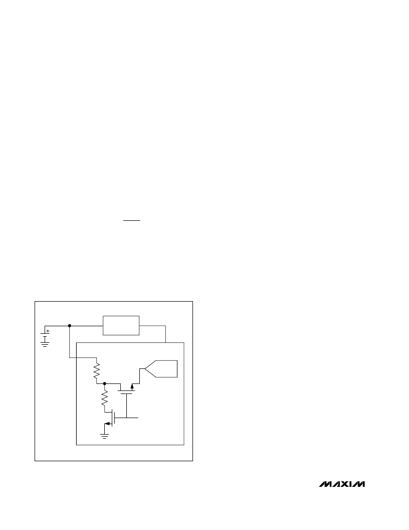
Battery Voltage Monitor
A dedicated analog input (BAT) allows the MXB7846 to
monitor the system battery voltage. Figure 8 shows the
battery voltage monitoring circuitry. The MXB7846 mon-
itors battery voltages from 0 to 6V. An internal resistor
network divides down V
BAT
by 4 so that a 6.0V battery
voltage results in 1.5V at the ADC input. To minimize
power consumption, the divider is only enabled during
the sampling of V
BAT
.
Internal Reference
Enable the internal 2.5V reference by setting PD1 in the
control byte to a logic 1 (see Tables 3 and 4). The
MXB7846 uses the internal reference for single-ended
measurement mode, battery monitoring, temperature
measurement, and for measurement on the auxiliary
input. To minimize power consumption, disable the inter-
nal reference by setting PD1 to a logic 0 when performing
ratiometric position measurements. The internal 2.5V ref-
erence typically requires 10ms to settle (with no external
load). For optimum performance, connect a 0.1μF capac-
itor from REF to GND. This internal reference can be over-
driven with an external reference. For best performance,
the internal reference should be disabled when the exter-
nal reference is applied. The internal reference of the
MXB7846 must also be disabled to maintain compatibility
with the MXB7843. To disable the internal reference of the
MXB7846 after power-up, a control byte with PD1 = 0 is
required. (See
Typical Operating Characteristics
for
power-up time of the reference from power down.)
External Reference
Although the internal reference may be overdriven with
an external reference, the internal reference should be
disabled (PD1 = 0) for best performance when using
an external reference. During conversion, an external
reference at REF must deliver up to 40μA DC load cur-
rent. If the reference has a higher output impedance or
is noisy, bypass it close to the REF pin with a 0.1μF and
a 4.7μF capacitor. Temperature measurements are
always performed using the internal reference.
Digital Interface
Initialization After Power-Up and Starting a
Conversion
The digital interface consists of three inputs, DIN, DCLK,
CS
, and one output, DOUT. A logic-high on
CS
disables
the MXB7846 digital interface and places DOUT in a
high-impedance state. Pulling
CS
low enables the
MXB7846 digital interface.
T C
(
T
T
VREF
4096
)
.
(
)
=
×
×
2 60
1
0
1000
273
DC/DC
CONVERTER
12-BIT ADC
BATTERY
0 TO 6.0V
0 TO 1.5V
2.5k
7.5k
+2.375V TO +5.25V
BAT
V
DD
BATTERY
MEASUREMENT ON
Figure 8. Battery Measurement Functional Block Diagram
相關(guān)PDF資料 |
PDF描述 |
|---|---|
| MXD1005PA__ | 5-Tap Silicon Delay Line |
| MXD1005PD__ | 5-Tap Silicon Delay Line |
| MXD1005SA__ | 5-Tap Silicon Delay Line |
| MXD1005SE__ | 5-Tap Silicon Delay Line |
| MXD1005UA__ | 5-Tap Silicon Delay Line |
相關(guān)代理商/技術(shù)參數(shù) |
參數(shù)描述 |
|---|---|
| MXB7846EUE+ | 功能描述:觸摸屏轉(zhuǎn)換器和控制器 2.375-5.25V 4-Wire Touch-Screen Ctlr RoHS:否 制造商:Microchip Technology 類型:Resistive Touch Controllers 輸入類型:3 Key 數(shù)據(jù)速率:140 SPS 分辨率:10 bit 接口類型:4-Wire, 5-Wire, 8-Wire, I2C, SPI 電源電壓:2.5 V to 5.25 V 電源電流:17 mA 工作溫度:- 40 C to + 85 C 封裝 / 箱體:SSOP-20 |
| MXB7846EUE+T | 功能描述:觸摸屏轉(zhuǎn)換器和控制器 2.375-5.25V 4-Wire Touch-Screen Ctlr RoHS:否 制造商:Microchip Technology 類型:Resistive Touch Controllers 輸入類型:3 Key 數(shù)據(jù)速率:140 SPS 分辨率:10 bit 接口類型:4-Wire, 5-Wire, 8-Wire, I2C, SPI 電源電壓:2.5 V to 5.25 V 電源電流:17 mA 工作溫度:- 40 C to + 85 C 封裝 / 箱體:SSOP-20 |
| MXB7846EUE-T | 功能描述:觸摸屏轉(zhuǎn)換器和控制器 RoHS:否 制造商:Microchip Technology 類型:Resistive Touch Controllers 輸入類型:3 Key 數(shù)據(jù)速率:140 SPS 分辨率:10 bit 接口類型:4-Wire, 5-Wire, 8-Wire, I2C, SPI 電源電壓:2.5 V to 5.25 V 電源電流:17 mA 工作溫度:- 40 C to + 85 C 封裝 / 箱體:SSOP-20 |
| MXB7846EVC16 | 功能描述:數(shù)據(jù)轉(zhuǎn)換 IC 開發(fā)工具 MXB7846C16 Eval Kit RoHS:否 制造商:Texas Instruments 產(chǎn)品:Demonstration Kits 類型:ADC 工具用于評估:ADS130E08 接口類型:SPI 工作電源電壓:- 6 V to + 6 V |
| MXB7846EVKIT | 功能描述:開發(fā)板和工具包 - 其他處理器 Programmers, Development Systems RoHS:否 制造商:Freescale Semiconductor 產(chǎn)品:Development Systems 工具用于評估:P3041 核心:e500mc 接口類型:I2C, SPI, USB 工作電源電壓: |
發(fā)布緊急采購,3分鐘左右您將得到回復(fù)。