- 您現在的位置:買賣IC網 > PDF目錄383644 > MT90401 (Mitel Networks Corporation) SONET/SDH System Synchronizer(SONET/SDH 系統(tǒng)同步裝置(由一個數字鎖相環(huán)組成)) PDF資料下載
參數資料
| 型號: | MT90401 |
| 廠商: | Mitel Networks Corporation |
| 英文描述: | SONET/SDH System Synchronizer(SONET/SDH 系統(tǒng)同步裝置(由一個數字鎖相環(huán)組成)) |
| 中文描述: | 的SONET / SDH系統(tǒng)的同步器(SONET / SDH的系統(tǒng)同步裝置(由一個數字鎖相環(huán)組成)) |
| 文件頁數: | 4/9頁 |
| 文件大?。?/td> | 110K |
| 代理商: | MT90401 |
MT90401
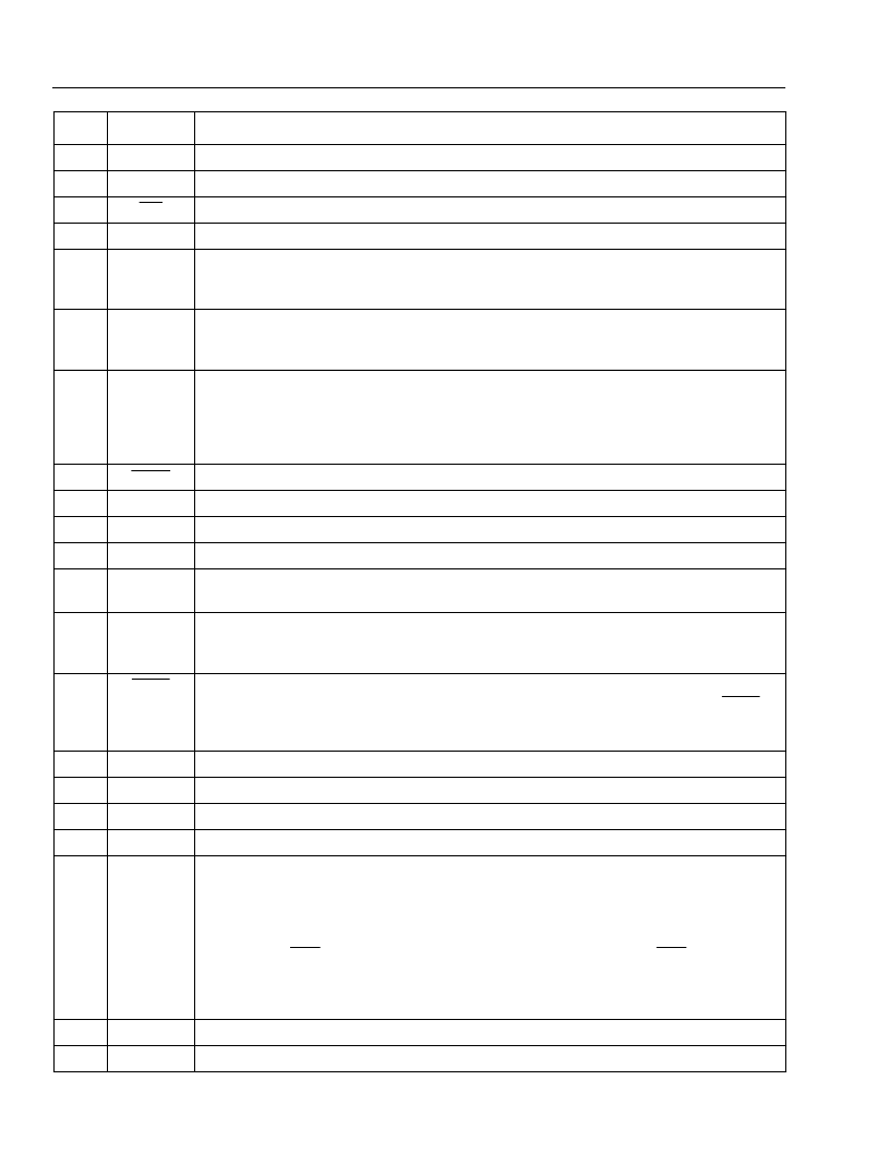
Pin Description (continued)
Product Brief
4
35
Tms
IEEE 1149.1a Test Mode Selection (Input)
. If not used, this pin should be pulled high.
36
Tclk
IEEE 1149.1a Test Clock Signal (Input)
. If not used, this pin should be pulled high.
37
Trst
IEEE 1149.1a Reset Signal (Input).
If not used, this pin should be held low.
38
Tdi
IEEE 1149.1a Test Data Input (Input).
If not used, this pin should be pulled high.
39
FS2
Frequency Select 2 (Input).
This input, in conjunction with FS1, selects which of four
possible frequencies (8kHz, 1.544MHz, 2.048MHz or 19.44MHz) may be input to the PRI
and SEC inputs.
40
FS1
Frequency Select 1 (Input).
This input, in conjunction with FS2, selects which of four
possible frequencies (8kHz, 1.544MHz, 2.048MHz or 19.44MHz) may be input to the PRI
and SEC inputs.
41
PRIOOR
Primary Reference Out Of Range (CMOS Output).
A logic high at this pin indicates that
the primary reference is off the PLL center frequency by more than 12 ppm. The calibration
is done on a 1 second basis using a signal derived from the 20MHz clock input on C20i.
When the accuracy of the 20MHz clock is
±
4.6ppm the effective out of range limits of the
PRIOOR pin will be
±
16.6
ppm.
Clock 1.544MHz (CMOS Output).
This output is used in T1 applications.
42
C1.5o
43
C6
Clock 6.312MHz (CMOS Output).
This output is used for DS2 or J2 applications.
44
IC
Internal Connection.
Tie low for normal operation
.
45
VSS
5
C19o
Digital ground.
0 Volts
46
Clock 19.44MHz (CMOS Output).
This output is used in OCN/STS-N and STM-N
applications.
47
RSEL
Reference Source Select (Input).
A logic low selects the PRI (primary) reference source
as the input reference signal and a logic high selects the SEC (secondary) input. The logic
level at this input is gated in by the rising edge of F8o.
48
TCLR
TIE Circuit Clear (Input).
A logic low at this input clears the Time Interval Error (TIE)
correction circuit resulting in a realignment of output phase with input phase. The TCLR pin
should be held low for a minimum of 300ns. When this pin is held low, the time interval error
correction circuit is disabled.
Positive Power Supply. Digital supply
(+3.3V
±
5%).
Digital ground.
0 Volts.
49
VDD
3
VSS
6
C20i
50
51
20 MHz Clock Input (5V tolerant Input).
This pin is the input for the master 20MHz clock.
52
V
SS7
C34/C44
Digital ground.
0Volts
53
Controlled Clock 34.368MHz / Clock 44.736MHz (CMOS Output).
This output clock is
programmable to be either 34.368MHz (for E3 applications) or 44.736MHz (for DS3
applications). The output clock is controlled via control pins in Hardware Mode or control
bits when the device is in Microport Mode.
If the E3DS3/OC3 control pin (in hardware mode) or if the E3DS3/OC3 control bit (in
microport mode) is high, the C34/C44 pin will output its nominal frequency. If the E3DS3/
OC3 control pin or control bit is low, the C34/C44 pin will output its nominal frequency
divided by 4. (C8.5o/C11o)
Positive Power Supply.
Digital supply (+3.3V
±
5%).
HOLDOVER
Holdover (CMOS Output).
This output goes high when the device is in holdover mode.
54
V
DD4
55
Pin #
Name
Description
相關PDF資料 |
PDF描述 |
|---|---|
| MT9040 | T1/E1 Synchronizer(T1/E1 系統(tǒng)同步裝置(由一個數字鎖相環(huán)組成)) |
| MT9041A | () |
| MT9041B | T1/E1 System Synchronizer(T1/E1系統(tǒng)同步裝置(由一個數字鎖相環(huán)組成)) |
| MT9042B | () |
| MT9042C | Multitrunk System Synchronizer(多中繼系統(tǒng)同步裝置) |
相關代理商/技術參數 |
參數描述 |
|---|---|
| MT90401AB | 制造商:ZARLINK 制造商全稱:Zarlink Semiconductor Inc 功能描述:SONET/SDH System Synchronizer |
| MT90401AB1 | 制造商:Microsemi Corporation 功能描述:FRAMER SDH/SONET 3.3V 80LQFP EP - Trays 制造商:MICROSEMI CONSUMER MEDICAL PRODUCT GROUP 功能描述:IC SYNCHRONIZER SONET/SDH 80LQFP 制造商:Microsemi Corporation 功能描述:IC SYNCHRONIZER SONET/SDH 80LQFP |
| MT9040AN | 制造商:ZARLINK 制造商全稱:Zarlink Semiconductor Inc 功能描述:T1/E1 Synchronizer |
| MT9040AN1 | 制造商:Microsemi Corporation 功能描述:FRAMER E1 /T1 3.3V 48SSOP - Rail/Tube |
| MT9040ANR1 | 制造商:Microsemi Corporation 功能描述:FRAMER E1 /T1 3.3V 48SSOP - Tape and Reel |
發(fā)布緊急采購,3分鐘左右您將得到回復。