- 您現(xiàn)在的位置:買賣IC網(wǎng) > PDF目錄69037 > MSC8101VT1500F (FREESCALE SEMICONDUCTOR INC) 64-BIT, 75 MHz, OTHER DSP, PBGA332 PDF資料下載
參數(shù)資料
| 型號(hào): | MSC8101VT1500F |
| 廠商: | FREESCALE SEMICONDUCTOR INC |
| 元件分類: | 數(shù)字信號(hào)處理 |
| 英文描述: | 64-BIT, 75 MHz, OTHER DSP, PBGA332 |
| 封裝: | 17 X 17 MM, LIDDED FLIP CHIP, PLASTIC, BGA-332 |
| 文件頁(yè)數(shù): | 15/104頁(yè) |
| 文件大?。?/td> | 1811K |
| 代理商: | MSC8101VT1500F |
第1頁(yè)第2頁(yè)第3頁(yè)第4頁(yè)第5頁(yè)第6頁(yè)第7頁(yè)第8頁(yè)第9頁(yè)第10頁(yè)第11頁(yè)第12頁(yè)第13頁(yè)第14頁(yè)當(dāng)前第15頁(yè)第16頁(yè)第17頁(yè)第18頁(yè)第19頁(yè)第20頁(yè)第21頁(yè)第22頁(yè)第23頁(yè)第24頁(yè)第25頁(yè)第26頁(yè)第27頁(yè)第28頁(yè)第29頁(yè)第30頁(yè)第31頁(yè)第32頁(yè)第33頁(yè)第34頁(yè)第35頁(yè)第36頁(yè)第37頁(yè)第38頁(yè)第39頁(yè)第40頁(yè)第41頁(yè)第42頁(yè)第43頁(yè)第44頁(yè)第45頁(yè)第46頁(yè)第47頁(yè)第48頁(yè)第49頁(yè)第50頁(yè)第51頁(yè)第52頁(yè)第53頁(yè)第54頁(yè)第55頁(yè)第56頁(yè)第57頁(yè)第58頁(yè)第59頁(yè)第60頁(yè)第61頁(yè)第62頁(yè)第63頁(yè)第64頁(yè)第65頁(yè)第66頁(yè)第67頁(yè)第68頁(yè)第69頁(yè)第70頁(yè)第71頁(yè)第72頁(yè)第73頁(yè)第74頁(yè)第75頁(yè)第76頁(yè)第77頁(yè)第78頁(yè)第79頁(yè)第80頁(yè)第81頁(yè)第82頁(yè)第83頁(yè)第84頁(yè)第85頁(yè)第86頁(yè)第87頁(yè)第88頁(yè)第89頁(yè)第90頁(yè)第91頁(yè)第92頁(yè)第93頁(yè)第94頁(yè)第95頁(yè)第96頁(yè)第97頁(yè)第98頁(yè)第99頁(yè)第100頁(yè)第101頁(yè)第102頁(yè)第103頁(yè)第104頁(yè)
MSC8101 Technical Data, Rev. 18
1-14
Freescale Semiconductor
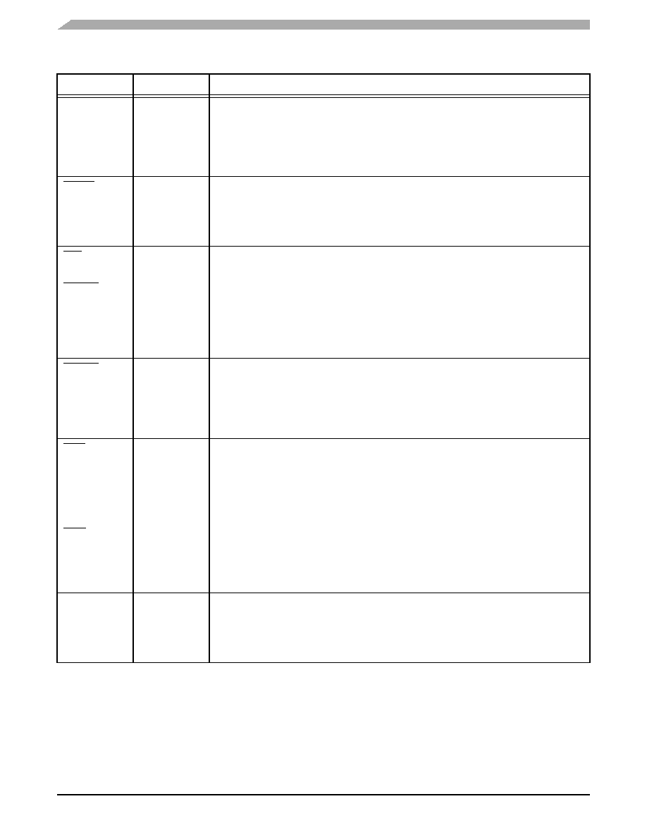
Signals/Connections
PSDA10
PGPL0
Output
Bus SDRAM A10
Output from the bus SDRAM controller. This pin is part of the address when a row address is driven.
It is part of the command when a column address is driven.
Bus UPM General-Purpose Line 0
One of six general-purpose output lines of the UPM. The values and timing of this pin are
programmed in the UPM.
PSDWE
PGPL1
Output
Bus SDRAM Write Enable
Output from the bus SDRAM controller. This pin should connect to the SDRAM WE input signal.
Bus UPM General-Purpose Line 1
One of six general-purpose output lines from the UPM. The values and timing of this pin are
programmed in the UPM.
POE
PSDRAS
PGPL2
Output
Bus Output Enable
Output of the bus GPCM. Controls the output buffer of memory devices during read operations.
Bus SDRAM RAS
Output from the bus SDRAM controller. This pin should connect to the SDRAM Row Address Strobe
(RAS) input signal.
Bus UPM General-Purpose Line 2
One of six general-purpose output lines from the UPM. The values and timing of this pin are
programmed in the UPM.
PSDCAS
PGPL3
Output
Bus SDRAM CAS
Output from the bus SDRAM controller. This pin should connect to the SDRAM Column Address
Strobe (CAS) input signal.
Bus UPM General-Purpose Line 3
One of six general-purpose output lines from the UPM. The values and timing of this pin are
programmed in the UPM.
PGTA
PUPMWAIT
PPBS
PGPL4
Input
Output
GPCM TA
Terminates transactions during GPCM operation. Requires an external pull up resistor for proper
operation.
Bus UPM Wait
Input to the UPM. An external device can hold this pin high to force the UPM to wait until the device
is ready for the operation to continue.
Bus Parity Byte Select
In systems that store data parity in a separate chip, this output is the byte-select for that chip.
Bus UPM General-Purpose Line 4
One of six general-purpose output lines from the UPM. The values and timing of this pin are
programmed in the UPM.
PSDAMUX
PGPL5
Output
Bus SDRAM Address Multiplexer
Controls the SDRAM address multiplexer when the MSC8101 is in External Master mode.
Bus UPM General-Purpose Line 5
One of six general-purpose output lines from the UPM. The values and timing of this pin are
programmed in the UPM.
Table 1-6.
Memory Controller Signals (Continued)
Signal
Data Flow
Description
相關(guān)PDF資料 |
PDF描述 |
|---|---|
| MSC8101M1375F | 64-BIT, 68.75 MHz, OTHER DSP, PBGA332 |
| MSC8126VT8000 | 0-BIT, 500 MHz, OTHER DSP, PBGA431 |
| MSC8126TMP6400 | 0-BIT, 400 MHz, OTHER DSP, PBGA431 |
| MSM5055 | 4-BIT, MROM, 0.032768 MHz, MICROCONTROLLER, UUC94 |
| MSM6051L | 4-BIT, MROM, 0.032768 MHz, MICROCONTROLLER, UUC102 |
相關(guān)代理商/技術(shù)參數(shù) |
參數(shù)描述 |
|---|---|
| MSC8102 | 制造商:FREESCALE 制造商全稱:Freescale Semiconductor, Inc 功能描述:Quad Core 16-Bit Digital Signal Processor |
| MSC81020 | 制造商:STMICROELECTRONICS 制造商全稱:STMicroelectronics 功能描述:RF & MICROWAVE TRANSISTORS GENERAL PURPOSE AMPLIFIER APPLICATIONS |
| MSC8102M4000 | 制造商:FREESCALE 制造商全稱:Freescale Semiconductor, Inc 功能描述:Quad Core 16-Bit Digital Signal Processor |
| MSC8102M4400 | 制造商:FREESCALE 制造商全稱:Freescale Semiconductor, Inc 功能描述:Quad Core 16-Bit Digital Signal Processor |
| MSC8102RM | 制造商:FREESCALE 制造商全稱:Freescale Semiconductor, Inc 功能描述:Quad Core 16-Bit Digital Signal Processor |
發(fā)布緊急采購(gòu),3分鐘左右您將得到回復(fù)。