- 您現(xiàn)在的位置:買賣IC網(wǎng) > PDF目錄377970 > ML4813 (Fairchild Semiconductor Corporation) Flyback Power Factor Controller(倒轉(zhuǎn)功率因數(shù)控制器) PDF資料下載
參數(shù)資料
| 型號(hào): | ML4813 |
| 廠商: | Fairchild Semiconductor Corporation |
| 元件分類: | 基準(zhǔn)電壓源/電流源 |
| 英文描述: | Flyback Power Factor Controller(倒轉(zhuǎn)功率因數(shù)控制器) |
| 中文描述: | 反激式功率因數(shù)控制器(倒轉(zhuǎn)功率因數(shù)控制器) |
| 文件頁(yè)數(shù): | 8/15頁(yè) |
| 文件大?。?/td> | 265K |
| 代理商: | ML4813 |
第1頁(yè)第2頁(yè)第3頁(yè)第4頁(yè)第5頁(yè)第6頁(yè)第7頁(yè)當(dāng)前第8頁(yè)第9頁(yè)第10頁(yè)第11頁(yè)第12頁(yè)第13頁(yè)第14頁(yè)第15頁(yè)
ML4813
8
APPLICATIONS
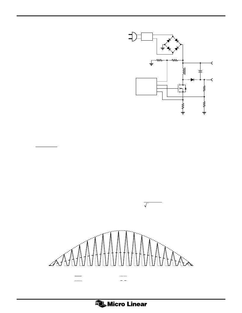
The ML4813 is used to implement a discontinuous mode
flyback (buck-boost) power factor regulator as shown in
Figure 7. This topology is particularly well suited for low
power applications such as fluorescent ballasts and low
power switching supplies. It is also a useful topology
when there is a requirement for the output voltage to be
lower than the peak input voltage, or where an isolated
output is required. This is not possible with a boost
topology, where the output voltage must always be higher
than the maximum peak of the input voltage range. The
typical input range for the flyback power factor regulator
is from 90VAC to 260VAC.
The regulator operates in the discontinuous current
conduction mode. The inductor energy stored during the
ON time of the power switch Q is completely delivered
to the output capacitance during the OFF time. Under
steady state conditions, the inductor current at the
beginning of the ON time starts to ramp-up from 0 Amps
to a value that is determined by the instantaneous value
of the input full wave rectified voltage; the ON time as it
is set by the error amplifier and the PWM comparator;
and finally by the inductor itself.
The expression for the inductor peak current is given by:
0 5
0 5
=
I
V
t
L
L
IN
ON
q
q
(4)
Where:
I
L
(
q
) = instantaneous peak inductor current
t
ON
= Power MOSFET "ON" time
V
IN
(
q
) = V
P
sin
q
= Instantaneous input voltage
V
P
= Input peak voltage
Figure 8 shows the relationship between the low
frequency envelope and the high frequency inductor
current. Note that for clarity the scale between the two
waveforms has not been preserved. Normally for 60Hz
input line and 100kHz switching frequency, each half of
the sine wave contains approximately 833 high frequency
triangular waveforms.
The envelope of the peaks of the switch current, which in
this case represents the current drawn from the input
source, has a sinewave shape. This relationship is shown
as:
0 5
=
sin
I
I
L
P
q
q
(5)
By combining (4) and (5), the following useful
relationship is obtained:
t
L
I
V
ON
P
RMS
=
2
(6)
Figure 8. Switch and Line Currents in the Flyback PFC Circuit
RFI
FILTER
ML4813
CONTROLLER
VOUT-
VOUT+
RS
RL2
RH2
C1
D1
Q1
L1
RH1
RL1
VS
–
+
INDUCTOR CURRENT
SWITCH CURRENT
SINUSOIDAL PEAK ENVELOPE
AVERAGE CURRENT
Figure 7. Simplified Application Circuit
相關(guān)PDF資料 |
PDF描述 |
|---|---|
| ML4819 | Power Factor and PWM Controller “Combo” |
| ML4819CP | Power Factor and PWM Controller “Combo” |
| ML4821 | Power Factor Controller |
| ML4821CP | Power Factor Controller |
| ML4821CS | Power Factor Controller |
相關(guān)代理商/技術(shù)參數(shù) |
參數(shù)描述 |
|---|---|
| ML4813CP | 制造商:MICRO-LINEAR 制造商全稱:MICRO-LINEAR 功能描述:Flyback Power Factor Controller |
| ML4813CS | 制造商:MICRO-LINEAR 制造商全稱:MICRO-LINEAR 功能描述:Flyback Power Factor Controller |
| ML4813IP | 制造商:MICRO-LINEAR 制造商全稱:MICRO-LINEAR 功能描述:Flyback Power Factor Controller |
| ML4813IS | 制造商:MICRO-LINEAR 制造商全稱:MICRO-LINEAR 功能描述:Flyback Power Factor Controller |
| ML4818 | 制造商:MICRO-LINEAR 制造商全稱:MICRO-LINEAR 功能描述:Phase Modulation/Soft Switching Controller |
發(fā)布緊急采購(gòu),3分鐘左右您將得到回復(fù)。
