- 您現(xiàn)在的位置:買(mǎi)賣(mài)IC網(wǎng) > PDF目錄377970 > ML4813 (Fairchild Semiconductor Corporation) Flyback Power Factor Controller(倒轉(zhuǎn)功率因數(shù)控制器) PDF資料下載
參數(shù)資料
| 型號(hào): | ML4813 |
| 廠商: | Fairchild Semiconductor Corporation |
| 元件分類: | 基準(zhǔn)電壓源/電流源 |
| 英文描述: | Flyback Power Factor Controller(倒轉(zhuǎn)功率因數(shù)控制器) |
| 中文描述: | 反激式功率因數(shù)控制器(倒轉(zhuǎn)功率因數(shù)控制器) |
| 文件頁(yè)數(shù): | 6/15頁(yè) |
| 文件大小: | 265K |
| 代理商: | ML4813 |
第1頁(yè)第2頁(yè)第3頁(yè)第4頁(yè)第5頁(yè)當(dāng)前第6頁(yè)第7頁(yè)第8頁(yè)第9頁(yè)第10頁(yè)第11頁(yè)第12頁(yè)第13頁(yè)第14頁(yè)第15頁(yè)
ML4813
6
FUNCTIONAL DESCRIPTION
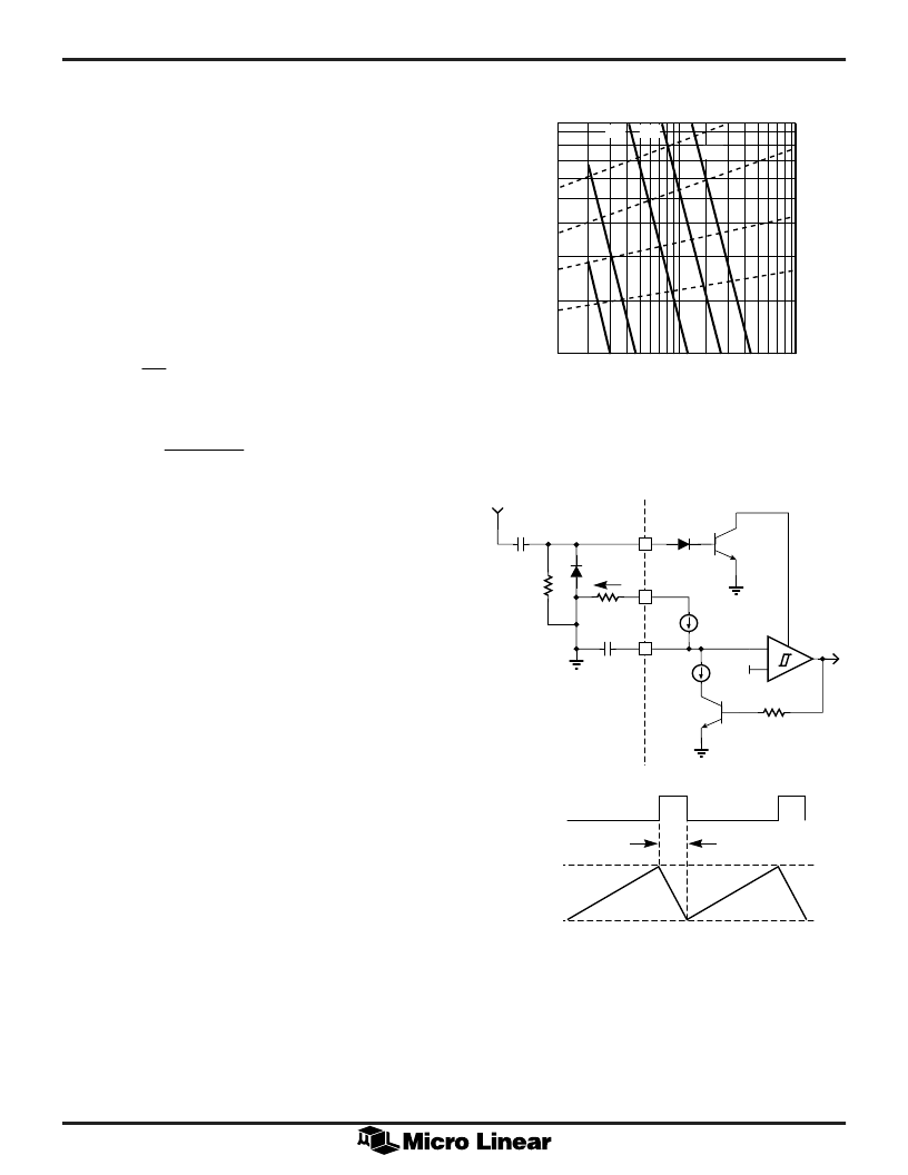
OSCILLATOR
The ML4813 oscillator charges the external capacitor (C
T
)
with a current (I
SET
) equal to 5/R
SET
. When the capacitor
voltage reaches the upper threshold, the comparator
changes state and the capacitor discharges to the lower
threshold through Q1. While the capacitor is discharging,
Q2 provides a high pulse.
The oscillator period can be described by:
t
t
t
OSC
RAMP
DEADTIME
=
+
(1)
where:
t
C
I
SET
RAMP
T
=
(2)
and:
t
C
mA
I
DEADTIME
T
SET
=
-
84
(3)
A graph showing the relationship between R
T
, C
T
, the
oscillator frequency, and maximum duty cycle is given in
Figure 1. A pulse of a duration shorter than t
DEADTIME
from an external frequency source set to a higher
frequency than f
OSC
can be applied to pin SYNC to
synchronize the oscillator. R
SYNC
and C
SYNC
shorten
longer pulses, as shown in Figure 2.
OUTPUT DRIVER STAGE
The ML4813 output driver is a 1A peak output high speed
totem-pole circuit designed to quickly drive capacitive
loads such as MOSFET gates. See Figure 3 for the output
saturation characteristics for sourcing and sinking current.
ERROR AMPLIFIER
The ML4813 error amplifier is a high open loop gain,
wide bandwidth amplifier. See Figure 4 for the gain and
phase plot.
UN-COMMITTED OP-AMP
The ML4813 contains an uncommitted op amp which is
normally configured as a differencing amplifier to sense
the output voltage. The output voltage in the flyback
configuration is not ground referenced. The op amp in the
ML4813 is a PNP input amplifier similar to the LM324
but with an open emitter class A output stage.
REFERENCE
The reference output voltage versus output current
characteristic is shown in Figure 5.
UNDERVOLTAGE LOCKOUT
On power-up, the ML4813 is in the UVLO condition;
Figure 1. Oscillator Timing Resistance vs. Frequency
Figure 2. Oscillator Block Diagram
10
SYNC
9
RT
16
CT
EXTERNAL
CLOCK
+
-
5.6V
ISET
8.4mA
CT
RT
ISET
CSYNC
RSYNC
CLOCK
TD
RAMP VALLEY
RAMP PEAK
V(CT)
10
R
)
OSCILLATOR FREQUENCY (kHz)
10
100
1000
8
5
3
2
1
M
10nF
20nF
5nF
2nF
1nF
85%
80%
70%
90%
output low and quiescent current low. The ML4813
becomes operational when V
CC
reaches 16V. When V
CC
drops below 10V, the UVLO condition is re-imposed.
During UVLO, the V
REF
pin is off, making it usable as a
"flag" for starting up a down-stream PWM converter.
相關(guān)PDF資料 |
PDF描述 |
|---|---|
| ML4819 | Power Factor and PWM Controller “Combo” |
| ML4819CP | Power Factor and PWM Controller “Combo” |
| ML4821 | Power Factor Controller |
| ML4821CP | Power Factor Controller |
| ML4821CS | Power Factor Controller |
相關(guān)代理商/技術(shù)參數(shù) |
參數(shù)描述 |
|---|---|
| ML4813CP | 制造商:MICRO-LINEAR 制造商全稱:MICRO-LINEAR 功能描述:Flyback Power Factor Controller |
| ML4813CS | 制造商:MICRO-LINEAR 制造商全稱:MICRO-LINEAR 功能描述:Flyback Power Factor Controller |
| ML4813IP | 制造商:MICRO-LINEAR 制造商全稱:MICRO-LINEAR 功能描述:Flyback Power Factor Controller |
| ML4813IS | 制造商:MICRO-LINEAR 制造商全稱:MICRO-LINEAR 功能描述:Flyback Power Factor Controller |
| ML4818 | 制造商:MICRO-LINEAR 制造商全稱:MICRO-LINEAR 功能描述:Phase Modulation/Soft Switching Controller |
發(fā)布緊急采購(gòu),3分鐘左右您將得到回復(fù)。