- 您現(xiàn)在的位置:買賣IC網(wǎng) > PDF目錄369914 > MCK12140D (MOTOROLA INC) PHASE-FREQUENCY DETECTOR PDF資料下載
參數(shù)資料
| 型號: | MCK12140D |
| 廠商: | MOTOROLA INC |
| 元件分類: | XO, clock |
| 英文描述: | PHASE-FREQUENCY DETECTOR |
| 中文描述: | PHASE DETECTOR, 650 MHz, PDSO8 |
| 封裝: | PLASTIC, SO-8 |
| 文件頁數(shù): | 3/4頁 |
| 文件大小: | 71K |
| 代理商: | MCK12140D |

MCH12140 MCK12140
3
MOTOROLA RF/IF DEVICE DATA
DC CHARACTERISTICS
(VEE = VEE(min) – VEE(max); VCC = GND, unless otherwise noted.)
–40
°
C
0
°
C
25
°
C
70
°
C
Characteristic
Symbol
Min
Typ
Max
Min
Typ
Max
Min
Typ
Max
Min
Typ
Max
Unit
Power Supply Current
H
K
IEE
45
45
38
38
45
45
52
52
38
38
45
45
52
52
38
42
45
50
52
58
mA
Power Supply Voltage
H
K
VEE
–4.75
–4.20
–5.2
–4.5
–5.5
–5.5
–4.75
–4.20
–5.2
–4.5
–5.5
–5.5
–4.75
–4.20
–5.2
–4.5
–5.5
–5.5
–4.75
–4.20
–5.2
–4.5
–5.5
–5.5
V
Input HIGH Current
IIH
150
150
150
150
μ
A
AC CHARACTERISTICS
(VEE = VEE(min) – VEE(max); VCC = GND, unless otherwise noted.
)
–40
°
C
0
°
C
25
°
C
70
°
C
Characteristic
Symbol
Min
Typ
Max
Min
Typ
Max
Min
Typ
Max
Min
Typ
Max
Unit
Maximum Toggle Frequency
FMAX
800
650
800
650
800
650
800
Propagation Delay
to Output
R to D
R to U
V to D
V to U
tPLH
tPHL
440
330
330
440
320
210
210
320
440
330
330
440
580
470
470
580
320
210
210
320
440
330
330
440
580
470
470
580
360
240
240
360
480
360
360
480
620
500
500
620
ps
Output Rise/Fall Times
Q (20 to 80%)
tr
tf
225
100
225
350
100
225
350
100
225
350
ps
APPLICATIONS INFORMATION
The 12140 is a high speed digital circuit used as a phase
comparator in an analog phase-locked loop. The device
determines the “l(fā)ead” or “l(fā)ag” phase relationship and time
difference between the leading edges of a VCO (V) signal
and a Reference (R) input. Since these edges occur only
once per cycle, the detector has a range of
±
2
π
radians.
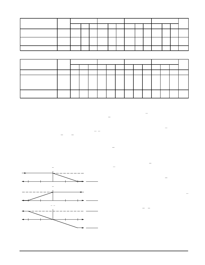
The operation of the 12140 can best be described using
the plots of Figure 1. Figure 1 plots the average value of U, D
and the difference between U and D versus the phase
difference between the V and R inputs.
There are four potential relationships between V and R: R
lags or leads V and the frequency of R is less than or greater
than the frequency of V. Under these four conditions the
12140 will function as follows:
Figure 1. Average Output Voltage versus
Phase Difference
U
R lags V
VOH – VOL
2
–2
π
–
π
π
2
π
Fv > Fr
VOH
Fv < Fr
R leads V
VOH – VOL
2
D
VOH
VOH – VOL
2
U–D
VOL – VOH
2
–2
π
–
π
π
2
π
–2
π
–
π
π
2
π
R lags V in phase
When the R and V inputs are equal in frequency and the
phase of R lags that of V the U output will stay HIGH while the
D output will pulse from HIGH to LOW. The magnitude of the
pulse will be proportional to the phase difference between the
V and R inputs reaching a minimum 50% duty cycle under a
180
°
out of phase condition. The signal on D indicates to the
VCO to decrease in frequency to bring the loop into lock.
V frequency > R frequency
When the frequency of V is greater than that of R the
12140 behaves in a simlar fashion as above. Again the signal
on D indicates that the VCO frequency must be decreased to
bring the loop into lock.
R leads V in phase
When the R and V inputs are equal in frequency and the
phase of R leads that of V the D output will stay HIGH while
the U output pulses from HIGH to LOW. The magnitude of the
pulse will be proportional to the phase difference between the
V and R inputs reaching a minimum 50% duty cycle under a
180
°
out of phase condition. The signal on U indicates to the
VCO to increase in frequency to bring the loop into lock.
V frequency < R frequency
When the frequency of V is less than that of R the 12140
behaves in a simlar fashion as above. Again the signal on U
indicates that the VCO frequency must be decreased to bring
the loop into lock.
From Figure 1 when V and R are at the same frequency
and in phase the value of U – D is zero thus providing a zero
error voltage to the VCO. This situation indicates the loop is
in lock and the 12140 action will maintain the loop in its
locked state.
相關(guān)PDF資料 |
PDF描述 |
|---|---|
| MCM54410AZ-80R2 | 1M x 4 CMOS Dynamic RAM Write Per Bit Mode |
| MCM54410AN-60 | 1M x 4 CMOS Dynamic RAM Write Per Bit Mode |
| MCM54410AN-70 | 1M x 4 CMOS Dynamic RAM Write Per Bit Mode |
| MCM54410AN-80 | 1M x 4 CMOS Dynamic RAM Write Per Bit Mode |
| MCM54410AN-80R2 | 1M x 4 CMOS Dynamic RAM Write Per Bit Mode |
相關(guān)代理商/技術(shù)參數(shù) |
參數(shù)描述 |
|---|---|
| MCK12140DG | 功能描述:相位探測器 / 移相器 Phase Freq. Detector RoHS:否 制造商:M/A-COM Technology Solutions 封裝 / 箱體:PQFN-24 封裝:Reel |
| MCK12140DR2 | 功能描述:相位探測器 / 移相器 Phase Freq. Detector RoHS:否 制造商:M/A-COM Technology Solutions 封裝 / 箱體:PQFN-24 封裝:Reel |
| MCK12140DR2G | 功能描述:相位探測器 / 移相器 Phase Freq. Detector RoHS:否 制造商:M/A-COM Technology Solutions 封裝 / 箱體:PQFN-24 封裝:Reel |
| MCK16Z1CFC16B1 | 制造商:FREESCALE 制造商全稱:Freescale Semiconductor, Inc 功能描述:M68HC16Z Series |
| MCK16Z1CFC20B1 | 制造商:FREESCALE 制造商全稱:Freescale Semiconductor, Inc 功能描述:Symbols and Operators, CPU16 Register Mnemonics |
發(fā)布緊急采購,3分鐘左右您將得到回復。