- 您現(xiàn)在的位置:買賣IC網(wǎng) > PDF目錄1949 > MC68MH360CZQ25L (Freescale Semiconductor)IC MPU QUICC 25MHZ 357-PBGA PDF資料下載
參數(shù)資料
| 型號: | MC68MH360CZQ25L |
| 廠商: | Freescale Semiconductor |
| 文件頁數(shù): | 106/158頁 |
| 文件大小: | 0K |
| 描述: | IC MPU QUICC 25MHZ 357-PBGA |
| 標準包裝: | 44 |
| 系列: | M683xx |
| 處理器類型: | M683xx 32-位 |
| 速度: | 25MHz |
| 電壓: | 5V |
| 安裝類型: | 表面貼裝 |
| 封裝/外殼: | 357-BBGA |
| 供應商設備封裝: | 357-PBGA(25x25) |
| 包裝: | 托盤 |
第1頁第2頁第3頁第4頁第5頁第6頁第7頁第8頁第9頁第10頁第11頁第12頁第13頁第14頁第15頁第16頁第17頁第18頁第19頁第20頁第21頁第22頁第23頁第24頁第25頁第26頁第27頁第28頁第29頁第30頁第31頁第32頁第33頁第34頁第35頁第36頁第37頁第38頁第39頁第40頁第41頁第42頁第43頁第44頁第45頁第46頁第47頁第48頁第49頁第50頁第51頁第52頁第53頁第54頁第55頁第56頁第57頁第58頁第59頁第60頁第61頁第62頁第63頁第64頁第65頁第66頁第67頁第68頁第69頁第70頁第71頁第72頁第73頁第74頁第75頁第76頁第77頁第78頁第79頁第80頁第81頁第82頁第83頁第84頁第85頁第86頁第87頁第88頁第89頁第90頁第91頁第92頁第93頁第94頁第95頁第96頁第97頁第98頁第99頁第100頁第101頁第102頁第103頁第104頁第105頁當前第106頁第107頁第108頁第109頁第110頁第111頁第112頁第113頁第114頁第115頁第116頁第117頁第118頁第119頁第120頁第121頁第122頁第123頁第124頁第125頁第126頁第127頁第128頁第129頁第130頁第131頁第132頁第133頁第134頁第135頁第136頁第137頁第138頁第139頁第140頁第141頁第142頁第143頁第144頁第145頁第146頁第147頁第148頁第149頁第150頁第151頁第152頁第153頁第154頁第155頁第156頁第157頁第158頁
Chapter 2. QMC Memory Organization
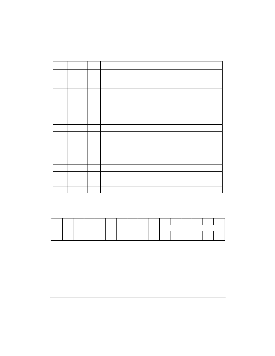
2.4.2.1 CHAMR—Channel Mode Register (Transparent Mode)
The channel mode register is a word-length, host-initialized register. Figure 2-11 shows the
channel mode register for transparent mode.
Notes: 1. All bits dened as reserved are cleared (0).
2. For the 68360, the bit numbering is reversed. See Appendix A for more information.
Figure 2-11. CHAMR—Channel Mode Register (Transparent Mode)
Table 2-11 describes the channel mode register’s elds for transparent operation. Boldfaced
parameters must be initialized by the user.
22
TMRBLR
16
Transparent maximum receive buffer length (host-initialized entry)—Denes the
maximum number of bytes written to a receive buffer before moving to the next
buffer for this channel. Note that this value must be a multiple of 4 bytes as the
QMC works on long-word alignment.
24
RSTATE
32
Rx internal state —Initialize to 0x3900
_0000 FC = 9, Motorola mode for MH360,
initialize to 0x3100
_0000 AT = 1, Motorola mode for 860MH. See Section 2.4.2.5,
“RSTATE—Rx Internal State (Transparent Mode),” for more information.
28
32
Rx internal data pointer—Points to current address of specic channel.
2C
RBPTR
16
Rx buffer descriptor pointer (host-initialized to RBASE, prior to operation or due to
a fatal error)—Contains the offset from MCBASE to the current receive buffer. See
Figure 2-2. MCBASE + RBPTR gives the address for the BD in use.
2E
16
Rx internal byte count—Per Channel: Number of remaining bytes in buffer
30
RPACK
32
(Rx temp)—Packs 4 bytes to 1 long word before writing to buffer.
34
ZDSTATE
32
Zero deletion machine state—(Host-initialized to 0x0000
_0080 in HDLC mode,
0x1800
_0080 in transparent mode, prior to operation and after a fatal Rx error
(global overrun, busy) before channel initialization.)—Contains the previous state
of the zero-deletion state machine. The middle 2 bytes, represented by zeros in the
initialization value above, holds the received pattern during reception. A window of
16 bits shows the history of what is received on this logical channel.
38
RES
32
3C
TRNSYNC
16
Transparent synchronization—In transparent mode, this register controls
synchronization for single time slots or superchannel applications. See
Section 2.4.2.4, “TRNSYNC—Transparent Synchronization.”
3E
RES
16
0
123456789
10
11
12
13
14
15
MODE
RD
1
ENT
RES’D
SYNC
RES
POL
0
RESERVED
0
Reset:
0
000000000000000
Table 2-10. Channel-Specific Transparent Parameters (Continued)
Offset
Name
Width
Description
F
re
e
sc
a
le
S
e
m
ic
o
n
d
u
c
to
r,
I
Freescale Semiconductor, Inc.
For More Information On This Product,
Go to: www.freescale.com
n
c
..
.
相關PDF資料 |
PDF描述 |
|---|---|
| MC68P11E1CFNE2R | IC MCU 8BIT 52-PLCC |
| MC68SEC000AA16R2 | IC MPU 32BIT 16 MHZ 64-QFP |
| MC705C8ACPE | IC MCU 4MHZ 8K OTP 40-DIP |
| MC705L16CFUE | IC MCU 8BIT EPROM 80-QFP |
| MC705X32VFUE | IC MCU 8BIT 32K FLASH 64-QFP |
相關代理商/技術參數(shù) |
參數(shù)描述 |
|---|---|
| MC68MH360EM25L | 功能描述:IC MPU QUICC ETHER 25MHZ 240FQFP RoHS:否 類別:集成電路 (IC) >> 嵌入式 - 微處理器 系列:M683xx 標準包裝:2 系列:MPC8xx 處理器類型:32-位 MPC8xx PowerQUICC 特點:- 速度:133MHz 電壓:3.3V 安裝類型:表面貼裝 封裝/外殼:357-BBGA 供應商設備封裝:357-PBGA(25x25) 包裝:托盤 |
| MC68MH360EM33K | 制造商:Motorola Inc 功能描述: |
| MC68MH360EM33L | 功能描述:IC MPU QUICC ETHER 33MHZ 240FQFP RoHS:否 類別:集成電路 (IC) >> 嵌入式 - 微處理器 系列:M683xx 標準包裝:2 系列:MPC8xx 處理器類型:32-位 MPC8xx PowerQUICC 特點:- 速度:133MHz 電壓:3.3V 安裝類型:表面貼裝 封裝/外殼:357-BBGA 供應商設備封裝:357-PBGA(25x25) 包裝:托盤 |
| MC68MH360FE33E | 制造商:Motorola Inc 功能描述: |
| MC68MH360RC25L | 功能描述:微處理器 - MPU QUICC 2SMC 1SPI RoHS:否 制造商:Atmel 處理器系列:SAMA5D31 核心:ARM Cortex A5 數(shù)據(jù)總線寬度:32 bit 最大時鐘頻率:536 MHz 程序存儲器大小:32 KB 數(shù)據(jù) RAM 大小:128 KB 接口類型:CAN, Ethernet, LIN, SPI,TWI, UART, USB 工作電源電壓:1.8 V to 3.3 V 最大工作溫度:+ 85 C 安裝風格:SMD/SMT 封裝 / 箱體:FBGA-324 |
發(fā)布緊急采購,3分鐘左右您將得到回復。