- 您現(xiàn)在的位置:買賣IC網(wǎng) > PDF目錄45228 > MC68HC711E20CFU2 (FREESCALE SEMICONDUCTOR INC) 8-BIT, OTPROM, 2 MHz, MICROCONTROLLER, PQFP64 PDF資料下載
參數(shù)資料
| 型號: | MC68HC711E20CFU2 |
| 廠商: | FREESCALE SEMICONDUCTOR INC |
| 元件分類: | 微控制器/微處理器 |
| 英文描述: | 8-BIT, OTPROM, 2 MHz, MICROCONTROLLER, PQFP64 |
| 封裝: | QFP-64 |
| 文件頁數(shù): | 44/242頁 |
| 文件大小: | 1672K |
| 代理商: | MC68HC711E20CFU2 |
第1頁第2頁第3頁第4頁第5頁第6頁第7頁第8頁第9頁第10頁第11頁第12頁第13頁第14頁第15頁第16頁第17頁第18頁第19頁第20頁第21頁第22頁第23頁第24頁第25頁第26頁第27頁第28頁第29頁第30頁第31頁第32頁第33頁第34頁第35頁第36頁第37頁第38頁第39頁第40頁第41頁第42頁第43頁當(dāng)前第44頁第45頁第46頁第47頁第48頁第49頁第50頁第51頁第52頁第53頁第54頁第55頁第56頁第57頁第58頁第59頁第60頁第61頁第62頁第63頁第64頁第65頁第66頁第67頁第68頁第69頁第70頁第71頁第72頁第73頁第74頁第75頁第76頁第77頁第78頁第79頁第80頁第81頁第82頁第83頁第84頁第85頁第86頁第87頁第88頁第89頁第90頁第91頁第92頁第93頁第94頁第95頁第96頁第97頁第98頁第99頁第100頁第101頁第102頁第103頁第104頁第105頁第106頁第107頁第108頁第109頁第110頁第111頁第112頁第113頁第114頁第115頁第116頁第117頁第118頁第119頁第120頁第121頁第122頁第123頁第124頁第125頁第126頁第127頁第128頁第129頁第130頁第131頁第132頁第133頁第134頁第135頁第136頁第137頁第138頁第139頁第140頁第141頁第142頁第143頁第144頁第145頁第146頁第147頁第148頁第149頁第150頁第151頁第152頁第153頁第154頁第155頁第156頁第157頁第158頁第159頁第160頁第161頁第162頁第163頁第164頁第165頁第166頁第167頁第168頁第169頁第170頁第171頁第172頁第173頁第174頁第175頁第176頁第177頁第178頁第179頁第180頁第181頁第182頁第183頁第184頁第185頁第186頁第187頁第188頁第189頁第190頁第191頁第192頁第193頁第194頁第195頁第196頁第197頁第198頁第199頁第200頁第201頁第202頁第203頁第204頁第205頁第206頁第207頁第208頁第209頁第210頁第211頁第212頁第213頁第214頁第215頁第216頁第217頁第218頁第219頁第220頁第221頁第222頁第223頁第224頁第225頁第226頁第227頁第228頁第229頁第230頁第231頁第232頁第233頁第234頁第235頁第236頁第237頁第238頁第239頁第240頁第241頁第242頁

Timing Systems
M68HC11E Family Data Sheet, Rev. 5.1
138
Freescale Semiconductor
9.4.7 Timer Interrupt Mask 1 Register
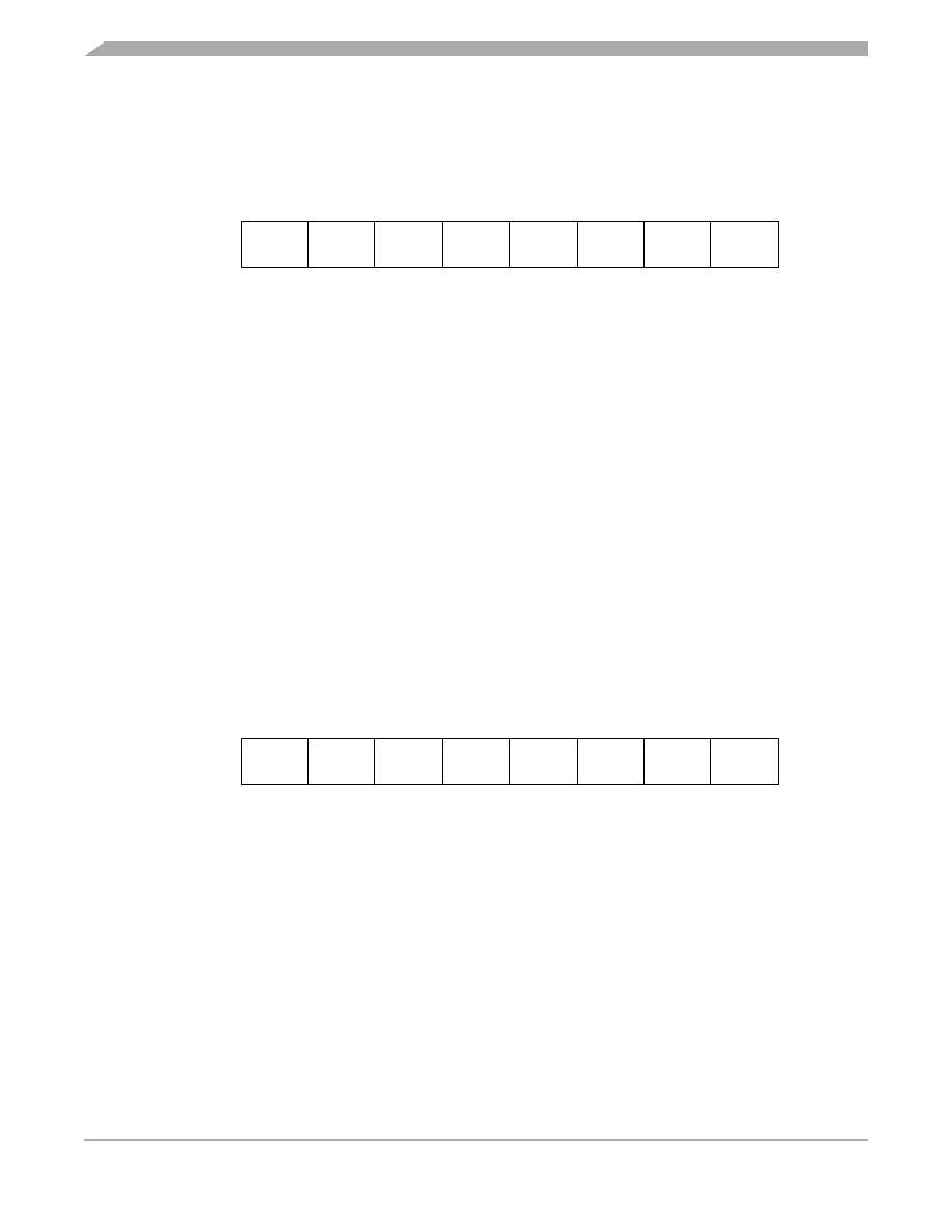
Use this 8-bit register to enable or inhibit the timer input capture and output compare interrupts.
OC1I–OC4I — Output Compare x Interrupt Enable Bits
If the OCxI enable bit is set when the OCxF flag bit is set, a hardware interrupt sequence is requested.
I4/O5I — Input Capture 4/Output Compare 5 Interrupt Enable Bit
When I4/O5 in PACTL is 1, I4/O5I is the input capture 4 interrupt enable bit. When I4/O5 in PACTL is
0, I4/O5I is the output compare 5 interrupt enable bit.
IC1I–IC3I — Input Capture x Interrupt Enable Bits
If the ICxI enable bit is set when the ICxF flag bit is set, a hardware interrupt sequence is requested.
NOTE
Bits in TMSK1 correspond bit for bit with flag bits in TFLG1. Bits in TMSK1
enable the corresponding interrupt sources.
9.4.8 Timer Interrupt Flag 1 Register
Bits in this register indicate when timer system events have occurred. Coupled with the bits of TMSK1,
the bits of TFLG1 allow the timer subsystem to operate in either a polled or interrupt driven system. Each
bit of TFLG1 corresponds to a bit in TMSK1 in the same position.
Clear flags by writing a 1 to the corresponding bit position(s).
OC1F–OC4F — Output Compare x Flag
Set each time the counter matches output compare x value
I4/O5F — Input Capture 4/Output Compare 5 Flag
Set by IC4 or OC5, depending on the function enabled by I4/O5 bit in PACTL
IC1F–IC3F — Input Capture x Flag
Set each time a selected active edge is detected on the ICx input line
Address:
$1022
Bit 7
654321
Bit 0
Read:
OC1I
OC2I
OC3I
OC4I
I4/O5I
IC1I
IC2I
IC3I
Write:
Reset:
00000000
Figure 9-17. Timer Interrupt Mask 1 Register (TMSK1)
Address:
$1023
Bit 7
654321
Bit 0
Read:
OC1F
OC2F
OC3F
OC4F
I4/O5F
IC1F
IC2F
IC3F
Write:
Reset:
00000000
Figure 9-18. Timer Interrupt Flag 1 Register (TFLG1)
相關(guān)PDF資料 |
PDF描述 |
|---|---|
| MC68S711E9CFN2 | 8-BIT, OTPROM, 2 MHz, MICROCONTROLLER, PQCC52 |
| MC68HC11E9MPB2 | 8-BIT, MROM, 2 MHz, MICROCONTROLLER, PQFP52 |
| MC68HC711E9CFS2 | 8-BIT, UVPROM, 2 MHz, MICROCONTROLLER, CQCC52 |
| MC68L11E1PB2 | 8-BIT, 2 MHz, MICROCONTROLLER, PQFP52 |
| MC68HC11E9VFU2 | 8-BIT, MROM, 2 MHz, MICROCONTROLLER, PQFP64 |
相關(guān)代理商/技術(shù)參數(shù) |
參數(shù)描述 |
|---|---|
| MC68HC711E20CFU3 | 制造商:Rochester Electronics LLC 功能描述:8BIT, 20K EPROM, 768RAM. - Bulk 制造商:Freescale Semiconductor 功能描述: 制造商:Motorola Inc 功能描述: |
| MC68HC711E20CFU4 | 制造商:Freescale Semiconductor 功能描述: |
| MC68HC711E20VFN2 | 制造商:Motorola Inc 功能描述: |
| MC68HC711E9 K81H WAF | 制造商:Motorola Inc 功能描述: |
| MC68HC711E9CFN | 制造商:Rochester Electronics LLC 功能描述: |
發(fā)布緊急采購,3分鐘左右您將得到回復(fù)。