- 您現(xiàn)在的位置:買賣IC網(wǎng) > PDF目錄369900 > MC145446 (Motorola, Inc.) Single-Chip 300-Baud Modem with DTMF Transceiver PDF資料下載
參數(shù)資料
| 型號: | MC145446 |
| 廠商: | Motorola, Inc. |
| 英文描述: | Single-Chip 300-Baud Modem with DTMF Transceiver |
| 中文描述: | 單芯片300波特調(diào)制解調(diào)器的雙音多頻收發(fā)器 |
| 文件頁數(shù): | 10/14頁 |
| 文件大?。?/td> | 264K |
| 代理商: | MC145446 |

MC145446A
10
MOTOROLA
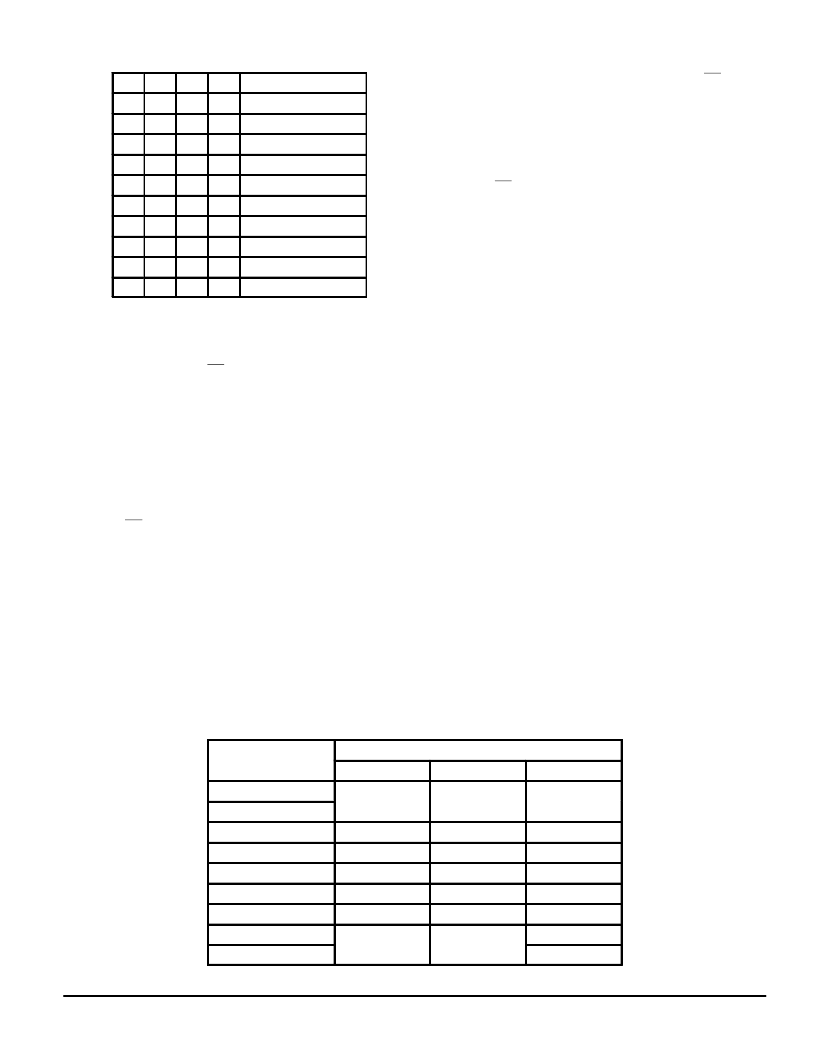
Table 1. Function Mode Truth Table
M3
M2
M1
M0
Function Mode
0
0
0
0
FSK
0
0
0
1
FSK Analog Loopback
0
0
1
0
CPTD
0
0
1
1
Answer Tone
0
1
0
0
DTMF Transmit
0
1
0
1
Single Tone
0
1
1
0
Power–Down 1
0
1
1
1
Power–Down 2
1
0
0
0
DTMF Receive
1
0
0
1
DTMF Analog Loopback
FSK Mode
The transmitter and the receiver work as an FSK modu-
lator/demodulator. The SD pin goes low when a valid FSK
signal is detected.
DTMF Transmit Mode
The transmitter works as a DTMF tone generator. The
receiver is disabled.
CPTD (Call Progress Tone Detect) Mode
The receiver works as a 400 Hz call progress tone detec-
tor. The CD pin goes low when a valid call progress tone is
detected.
Answer Tone Mode
The transmitter works as a 2100 Hz answer tone genera-
tor. The receiver is disabled.
FSK Analog Loopback Mode
The transmitter, working as the FSK modulator, is internal-
ly connected to the receiver working as the FSK demodula-
tor. This feature is used for the device self test.
DTMF Receive Mode
The receiver works as a DTMF tone receiver. The DV goes
low when a valid DTMF tone is detected. The transmitter is
disabled.
DTMF Analog Loopback Mode
The transmitter, working as a DTMF tone generator, is in-
ternally connected to the receiver working as DTMF tone re-
ceiver. The DV goes low when the receiver detects a valid
DTMF tone. This feature is used for the device self test.
Single Tone Mode
The transmitter generates one of the eight frequencies of
the DTMF tone. The receiver is disabled.
Power–Down Mode 1
Whole internal circuits, except the oscillator, are disabled
and all outputs except the X1 pin go to the high–impedance
state. The supply current decreases to 500
μ
A (max).
Power–Down Mode 2
Whole internal circuits, including the oscillator, are dis-
abled and all outputs go to the high–impedance state. The
supply current decreases to 1.0
μ
A (max).
Transmit Attenuator/AGC Gain Set (A3 to A0)
Four–bit serial data (A3 – A0) sets up the analog transmit
level in the FSK, answer tone, DTMF, analog loopback, and
single tone mode. The range of the transmit attenuator is 0 to
15 dB in 1 dB steps. The attenuator, however, does not affect
the external signal input from the DSI. These bits also deter-
mine the AGC amplifier gain in the DTMF receive mode. In
normal operation, “Automatic” may be selected so that the
gain is automatically adjusted corresponding to the input sig-
nal level. See Table 3 for a detailed description.
Transmit Tone Frequency (T3 to T0)
These four bits (T3 to T0) determine the DTMF tone fre-
quencies in DTMF transmit and DTMF analog loopback
mode, and determine the single tone frequency in the single
tone mode. Tone frequency assignments with reference to
T3 – T0 are shown in Table 4.
Table 2. Output Status
Function Mode
Output Pin
RxD
SD/CD/DV
TxA1, TxA2
FSK
Receive
Digital Data
Carrier
Detect Signal
FSK
FSK Loopback
Call Progress Tone
H
CPTD Signal
VCC/2
Answer Tone
Answer Tone
H
H
DTMF Transmit
H
H
DTMF Tone
Single Tone
H
H
Single Tone
Power–Down 1, 2
High Impedance
High Impedance
High Impedance
DTMF Receive
H
DV Signal
VCC/2
DTMF Tone
DTMF Loopback
相關(guān)PDF資料 |
PDF描述 |
|---|---|
| MC145447DW | Calling Line Identification(CLID) Receiver with Ring Detector |
| MC145447 | Calling Line Identification(CLID) Receiver with Ring Detector |
| MC145447P | Calling Line Identification(CLID) Receiver with Ring Detector |
| MC14544BCL | BCD-to-Seven Segment Latch/Decoder/Driver for Liquid Crystals |
| MC14544BCP | BCD-to-Seven Segment Latch/Decoder/Driver for Liquid Crystals |
相關(guān)代理商/技術(shù)參數(shù) |
參數(shù)描述 |
|---|---|
| MC145446AFW | 制造商:Rochester Electronics LLC 功能描述:- Bulk 制造商:Motorola Inc 功能描述: 制造商:MOTOROLA 功能描述: |
| MC145447DW | 制造商:Motorola Inc 功能描述:CALLER NUMBER ID CIRCUIT, 16 Pin, Plastic, SOP |
| MC145447DWR2 | 制造商:Motorola Inc 功能描述:TELEPHONE MULTIFUNCTION CKT, 16 Pin Plastic SOP |
| MC145447P | 制造商:Motorola Inc 功能描述: |
| MC145475DW | 制造商:Motorola Inc 功能描述:DATACOM, ISDN CONTROLLER, PDSO28 |
發(fā)布緊急采購,3分鐘左右您將得到回復(fù)。