- 您現(xiàn)在的位置:買(mǎi)賣(mài)IC網(wǎng) > PDF目錄379305 > MC141800AT (MOTOROLA INC) LCD Segment/Common Driver PDF資料下載
參數(shù)資料
| 型號(hào): | MC141800AT |
| 廠商: | MOTOROLA INC |
| 元件分類(lèi): | 顯示驅(qū)動(dòng)器 |
| 英文描述: | LCD Segment/Common Driver |
| 中文描述: | LIQUID CRYSTAL DISPLAY DRIVER, UUC236 |
| 封裝: | TAB-236 |
| 文件頁(yè)數(shù): | 19/32頁(yè) |
| 文件大小: | 541K |
| 代理商: | MC141800AT |
第1頁(yè)第2頁(yè)第3頁(yè)第4頁(yè)第5頁(yè)第6頁(yè)第7頁(yè)第8頁(yè)第9頁(yè)第10頁(yè)第11頁(yè)第12頁(yè)第13頁(yè)第14頁(yè)第15頁(yè)第16頁(yè)第17頁(yè)第18頁(yè)當(dāng)前第19頁(yè)第20頁(yè)第21頁(yè)第22頁(yè)第23頁(yè)第24頁(yè)第25頁(yè)第26頁(yè)第27頁(yè)第28頁(yè)第29頁(yè)第30頁(yè)第31頁(yè)第32頁(yè)
3–295
MC141800A
MOTOROLA
Set 4X / 5X DC/DC Converter
This command selects the usage of 4X or 5X Converter when the
Internal DC/DC Converter is enabled.
Set Temperature Coefficient
A temperature gradient selector circuit controlled by two control bits
TC1 and TC2. This command can select 4 different LCD driving voltage
temperature coefficients to match various liquid crystal temperature
grades.
Set Internal Regulator On/Off
Choose bit option 0 to disable the on chip Internal Regulator. Choose
bit option 1 to enables Internal Regulator which consists of the internal
contrast control circuits.
Set Smart Bias Divider On/Off
If the Smart Bias Divider is disabled, external bias can be used for
V
LL6
to V
LL2.
If the Smart Bias Divider is enabled, the internal circuit will
generated the 1:7 or 1:9 bias driving voltage.
End of Command
This command is used as extra write end command follows the last
byte of data / command written. This command is not available if serial
mode is selected.
Set Internal Contrast Control Enable
This command is used to adjust the delta voltage of the bias volt-
ages. With bit option = 1, the software selection for delta bias voltage
control is enabled. With bit option = 0, internal contrast control is dis-
abled.
Increase / Decrease Contrast Level
If the internal contrast control is enabled, this command is used to
increase or decrease the contrast level within the 16 contrast levels.
The contrast level starts from lowest value after POR.
Set Contrast Level
This command is to select one of the 16 contrast levels when internal
contrast control circuitry is in use. After power-on reset, the contrast
level is lowest.
Set Smart Icon Mode
This command is to set 4-Phase or 6-Phase smart icon modes which
for lower VDD or higher Von of panel. Refer to Smart Icon Mode Output
Description for detail.
Set Display Waveform Type
This command will select the number of lines for the polarity inver-
sion of the driving waveform. Four types of waveform types are avail-
able. Refer to Figure 9.
Set Data Direction
This command is used in SPI mode only. It will be two continuous
commands, the first byte control the data direction and inform the LCD
driver the second byte will be number of data bytes will be read / write.
After these two commands sending out, the following messages will be
data.
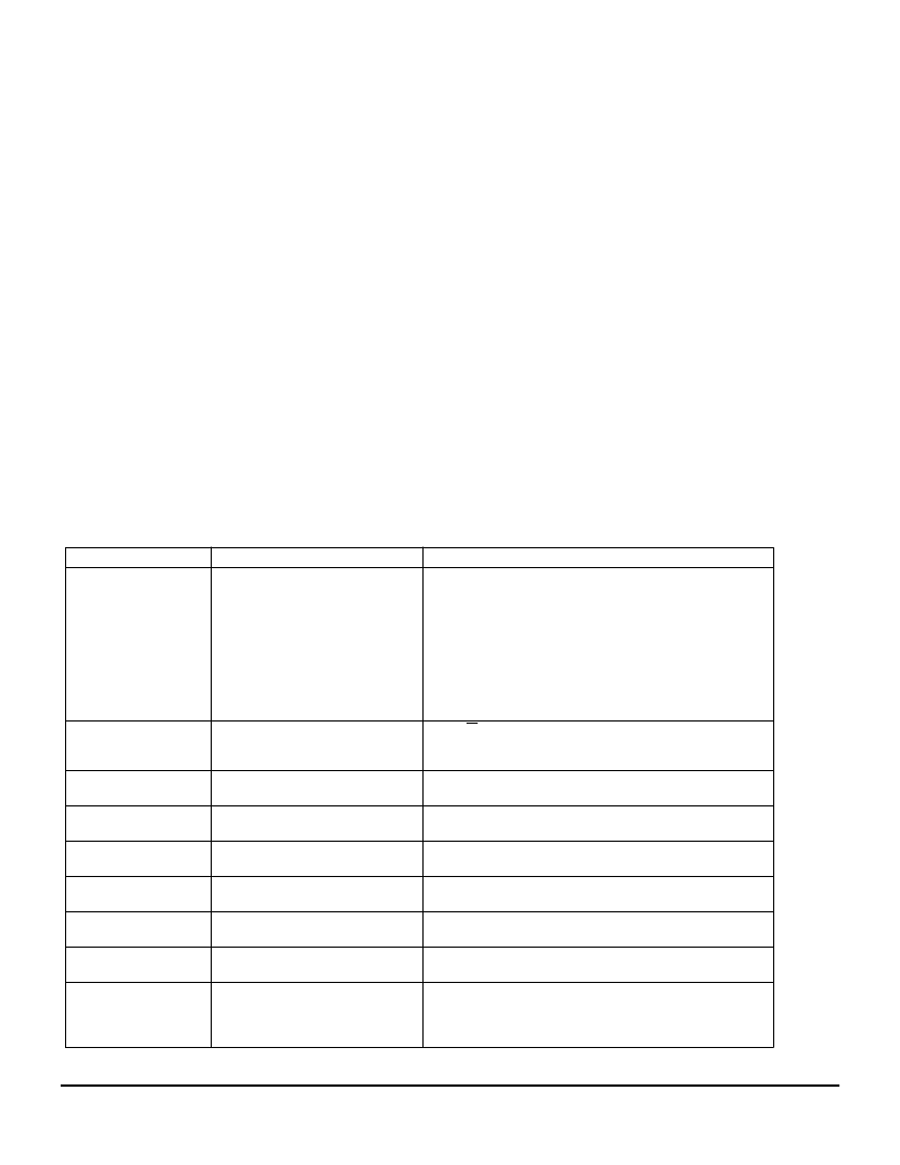
COMMAND TABLE
Bit Pattern
Command
Comment
0000X
3
X
2
X
1
X
0
Set GDDRAM Page Address
Set GDDRAM Page Address using X
3
X
2
X
1
X
0
as address bits.
X
3
X
2
X
1
X
0
=0000 : page 1 (POR)
X
3
X
2
X
1
X
0
=0001 : page 2
X
3
X
2
X
1
X
0
=0010 : page 3
X
3
X
2
X
1
X
0
=0011 : page 4
X
3
X
2
X
1
X
0
=0100 : page 5
X
3
X
2
X
1
X
0
=0101 : page 6
X
3
X
2
X
1
X
0
=0110 : page 7
X
3
X
2
X
1
X
0
=0111 : page 8
X
3
X
2
X
1
X
0
=1000 : page 9
With R/W pin input low, set one of the 16 available values to the
internal contrast register, using X
3
X
2
X
1
X
0
as data bits.
The contrast register is reset to 0000 during POR.
0001X
3
X
2
X
1
X
0
Set Contrast Level
0010000X
0
Set 4X / 5X DC-DC Converter
X
0
=0: enable 4X Converter (POR)
X
0
=1: enable 5X Converter
X
0
=0: Col0 to Seg0 (POR)
X
0
=1: Col0 to Seg127
X
0
=0: Row0 to Com0 (POR)
X
0
=1: Row0 to Com63
X
0
=0: display off (POR)
X
0
=1: display on
X
0
=0: Internal DC/DC Converter Off (POR)
X
0
=1: Internal DC/DC Converter On
X
0
=0: Internal Regulator Off(POR)
X
0
=1: Internal Regulator On
X
0
=0: Smart Bias Divider Off (POR)
X
0
=1: Smart Bias Divider On
When an external bias network is preferred, the Smart Bias
Divider should be disabled.
0010001X
0
Set Segment Mapping
0010010X
0
Set Common Mapping
0010100X
0
Set Display on/off
0010101X
0
Set Internal DC/DC Converter On/Off
0010110X
0
Set Internal Regulator On/Off
0010111X
0
Set Smart Bias Divider On/Off
相關(guān)PDF資料 |
PDF描述 |
|---|---|
| MCC141800AZ | LCD Segment/Common Driver |
| MC14194BCL | 4-Bit Bidirectional Universal Shift Register |
| MC14194BCP | MILITARY DIGITAL SIGNAL PROCESSORS 132-BQFP -55 to 125 |
| MC14194BD | 4-Bit Bidirectional Universal Shift Register |
| MC143421FU | PCI Bus Interface |
相關(guān)代理商/技術(shù)參數(shù) |
參數(shù)描述 |
|---|---|
| MC-141M | 制造商:Panasonic Industrial Company 功能描述:BAG |
| MC142236DW | 制造商:Motorola Inc 功能描述:142236DW |
| MC-1425-15-18 | 制造商:RRE 制造商全稱(chēng):RRE 功能描述:Miniature Close Differential Reed Switch |
| MC-142M | 制造商:Panasonic Industrial Company 功能描述:BAG |
| MC1430G | 制造商:Rochester Electronics LLC 功能描述:- Bulk |
發(fā)布緊急采購(gòu),3分鐘左右您將得到回復(fù)。