- 您現(xiàn)在的位置:買賣IC網(wǎng) > PDF目錄376151 > MC1141A (Electronic Theatre Controls, Inc.) Advanced Brushless Motor Control Chipset PDF資料下載
參數(shù)資料
| 型號(hào): | MC1141A |
| 廠商: | Electronic Theatre Controls, Inc. |
| 英文描述: | Advanced Brushless Motor Control Chipset |
| 中文描述: | 先進(jìn)的無刷電機(jī)控制芯片組 |
| 文件頁數(shù): | 35/70頁 |
| 文件大?。?/td> | 474K |
| 代理商: | MC1141A |
第1頁第2頁第3頁第4頁第5頁第6頁第7頁第8頁第9頁第10頁第11頁第12頁第13頁第14頁第15頁第16頁第17頁第18頁第19頁第20頁第21頁第22頁第23頁第24頁第25頁第26頁第27頁第28頁第29頁第30頁第31頁第32頁第33頁第34頁當(dāng)前第35頁第36頁第37頁第38頁第39頁第40頁第41頁第42頁第43頁第44頁第45頁第46頁第47頁第48頁第49頁第50頁第51頁第52頁第53頁第54頁第55頁第56頁第57頁第58頁第59頁第60頁第61頁第62頁第63頁第64頁第65頁第66頁第67頁第68頁第69頁第70頁

35
Phase A
Phase B
Phase C
90
180
270
360
3-Phase Brushless
Hall A
Hall B
Hall C
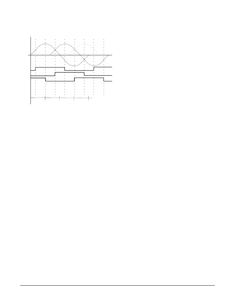
Unlike the algorithmc method, using Hall-based phase initialization no
special motor procedures are required. Initialization is performed using
the command INIT_PHASE, and occurs immediately, without any motor
motion.
To accommodate varying types of Hall sensors, or sensors that contain
inverter circuitry, the signal level/logic interpretation of the Hall sensor
input signals can be set through the host.
The command SET_HALL_SENSE accepts a bit-programmed word
which controls whether the incomng Hall signals are interpreted as
active high, or active low. To read back this Hall interpretation value
use the command GET_HALL_SENSE. For details on the programmng
of this control word see the Command Reference section of this
manual.
Hall-based initialization should only be used with a 3-phase
commutation waveform, and with Hall sensors located 120
degrees apart. Hall-sensors located 60 degrees apart should not
be used.
Mcrostepping Phase Initialization
If the location of the index pulse in relation to the motor rotor and case
is known then it may be advantageous to use an initialization technique
which operates the motor as a mcrostepper, rotating the motor until the
index pulse is found, and then setting the phase angle explicitly.
This scheme is only appropriate for motors which have the index pulse
in a fixed and repeatable location within the commutation cycle for all of
the motors to be used during manufacturing of the product. Although
this is relatively uncommon, it is typical for motors with optical Hall-
sensors which use a single disk containing the A, B, index, and Hall
sensor information.
To set the chipset for mcrostepping operation the command
SET_PHASE_MICRO is used. To restore the chipset for encoder-
based commutation the command SET_PHASE_ENC is used. Once
the index pulse is encountered the phase angle can be set using the
command SET_PHASE.
To operate the motor in mcrostepping mode the motor must be set on
(MTR_ON command), and a motor output value must be provided
(SET_BUF_MTR_CMD & UPDATE). In addition the #of encoder
counts per electrical cycle should be set to 512.
When in mcrostepping mode each trajectory 'count' corresponds to
1/256 of a full electrical cycle. For example using a 4-pole motor (2
electrical cycles per motor rotation) a trajectory move of 512 counts will
move the motor 1 full motor rotation.
Special care should be taken when initializing the motor using the
mcrostepping method. Because the motor is operated 'open-loop' the
resultant coil energization and subsequent rotation may be jerky and
abrupt.
Phase initialization using the microstepping method should only
be used under special circumstances. It is not generally
recommended unless the algorithmic or Hall-based methods can
not be used.
Direct-Set Phase Initialization
If, after power-up the location of the motor phasing is known explicitly
the phase angle can simply be set directly using the SET_PHASE
command.
This typically occurs when sensors such as resolvers are used where
the returned motor position information is absolute in nature (not
incremental) , and can be used to generate a quadrature data stream
as well as be read by the host directly.
Phase Initialization Programming
The following examples show typical host command sequences to
initialize the commutation of a brushless motor for all four initialization
methods.
Algorithmc Initialization Sequence
SET_PHASE_CNTS uuuu
Set #of encoder counts per electrical
cycle
Set phase initialization method to
algorithmc
Turn motor off so it doesn't conflict
with initialization procedure
Set algorithmc phase init duration
Set initialization motor command level
Performthe initialization
SET_PHASE_ALGOR
MTR_OFF
SET_PHASE_TIME wwww
SET_BUF_MTR_CMD xxxx
INIT_PHASE
This sequence will cause the motor to immediately begin the
initialization procedure, which will last 'wwww' servo loops long. To
determne if the procedure is completed, the command
相關(guān)PDF資料 |
PDF描述 |
|---|---|
| MC1151A | Advanced Brushless Motor Control Chipset |
| MC1151A-E | Advanced Brushless Motor Control Chipset |
| MC1201A | Advanced Brushless Motor Control Chipset |
| MC1201A-P | Advanced Brushless Motor Control Chipset |
| MC1231A | Advanced Brushless Motor Control Chipset |
相關(guān)代理商/技術(shù)參數(shù) |
參數(shù)描述 |
|---|---|
| MC11469 | 制造商:SPC Multicomp 功能描述:Mounting Bracket |
| MC11470 | 制造商:SPC Multicomp 功能描述:Mounting Bracket 制造商:SPC Multicomp 功能描述:MOUNTING BRACKET; Leaded Process Compatible:No; Peak Reflow Compatible (260 C):No; Accessory Type:Bracket; For Use With:Wirewound Resistors ;RoHS Compliant: No |
| MC11471 | 制造商:SPC Multicomp 功能描述: 制造商:PRIVATE LABEL 功能描述:MOUNTING BRACKET, Accessory Type:Bracket, For Use With:Wirewound Resistors, Lead |
| MC11472 | 制造商:PRIVATE LABEL 功能描述:MOUNTING BRACKET, Leaded Process Compatible:No, Peak Reflow Compatible (260 C):N |
| MC114N | 制造商:POSITR 功能描述: |
發(fā)布緊急采購(gòu),3分鐘左右您將得到回復(fù)。