- 您現(xiàn)在的位置:買賣IC網(wǎng) > PDF目錄377906 > MB89498PFV (FUJITSU LTD) 8-bit Proprietary Microcontroller CMOS PDF資料下載
參數(shù)資料
| 型號: | MB89498PFV |
| 廠商: | FUJITSU LTD |
| 元件分類: | 微控制器/微處理器 |
| 英文描述: | 8-bit Proprietary Microcontroller CMOS |
| 中文描述: | 8-BIT, MROM, 12.5 MHz, MICROCONTROLLER, PQFP100 |
| 封裝: | PLASTIC, LQFP-100 |
| 文件頁數(shù): | 3/57頁 |
| 文件大小: | 341K |
| 代理商: | MB89498PFV |
第1頁第2頁當前第3頁第4頁第5頁第6頁第7頁第8頁第9頁第10頁第11頁第12頁第13頁第14頁第15頁第16頁第17頁第18頁第19頁第20頁第21頁第22頁第23頁第24頁第25頁第26頁第27頁第28頁第29頁第30頁第31頁第32頁第33頁第34頁第35頁第36頁第37頁第38頁第39頁第40頁第41頁第42頁第43頁第44頁第45頁第46頁第47頁第48頁第49頁第50頁第51頁第52頁第53頁第54頁第55頁第56頁第57頁
MB89490 Series
3
I
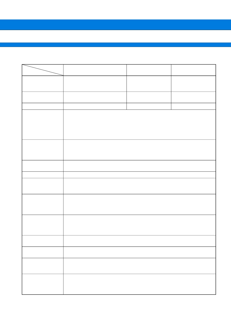
PRODUCT LINEUP
(Continued)
Part number
Parameter
MB89498
MB89F499
MB89PV490
Classification
Mass production products
(mask ROM product)
FLASH
Piggy-back
(For evaluation or
development)
60 K
×
8-bit
(external ROM) *
1
2 K
×
8-bit
ROM size
48 K
×
8-bit
(internal ROM)
2 K
×
8-bit
60 K
×
8-bit
(internal FLASH)
2 K
×
8-bit
: 136
: 8-bit
: 1 to 3 bytes
: 1-bit, 8-bit, 16-bit
: 0.32
μ
s/12.5 MHz
:
2.88
μ
s
/
12.5 MHz
: 56 pins
: 2 pins
: 8 pins
:
66 pins
RAM size
CPU functions
Number of instructions
Instruction bit length
Instruction length
Data bit length
Minimum instruction execution time
Minimum interrupt processing time
Ports
General-purpose I/O ports (CMOS)
Input ports (CMOS)
N-channel open drain I/O ports
Total
21-bit timebase
timer
Interrupt generation cycle (0.66 ms, 2.6 ms, 21.0 ms, 335.5 ms) at 12.5 MHz
Watchdog timer
Reset generation cycle (167.8 ms to 335.5 ms) at 12.5 MHz
PWM timer 0, 1
8-bit reload timer operation (supports square wave output and operating clock period :
1 t
inst
, 8 t
inst
, 16 t
inst
, 64 t
inst
)
8-bit accuracy PWM operation
8/16-bit timer/counter
00, 01
Can be operated either as a 2-channel 8-bit timer/counter (timer 00 and timer 01, each
with its own independent operating clock) , or as one 16-bit timer/counter.
In timer 00 or 16-bit timer/counter operation, event counter operation by external clock
input and square wave output capability
8/16-bit timer/counter
10, 11
Can be operated either as a 2-channel 8-bit timer/counter (timer 10 and timer 11, each
with its own independent operating clock) , or as one 16-bit timer/counter.
In timer 10-bit or 16-bit timer/counter operation, event counter operation by external clock
input and square wave output capability
External interrupt 0
(edge)
8 independent channels (selectable edge, interrupt vector, request flag)
External interrupt 1
(level)
8 channels (low level interrupt)
A/D converter
10-bit accuracy
×
8 channels
A/D conversion function (conversion time : 30 t
inst
)
Supports repeated activation by internal clock
LCD controller/driver
Common output
Segment output
LCD driving power (bias) pins
LCD display RAM size
: 4 (Max)
: 32 (Max)
: 3
: 32
×
4 bits
相關(guān)PDF資料 |
PDF描述 |
|---|---|
| MB89530A | 8-BIT MICROCONTROLLER |
| MB89530 | 8-bit Original Microcontroller |
| MB89537 | 8-bit Original Microcontroller |
| MB89537C | 8-bit Original Microcontroller |
| MB89537CP | 8-bit Original Microcontroller |
相關(guān)代理商/技術(shù)參數(shù) |
參數(shù)描述 |
|---|---|
| MB894-C6-R | 制造商:IBase Technology (USA) Inc. 功能描述:MATX, ZC CELERON M 600MHZ, 852GM, VGA, 10/100BT X 1, COMX4, - Bulk |
| MB894F-R | 制造商:IBase Technology (USA) Inc. 功能描述:MATX, SOCKET 479, 855GME, VGA, 10/100BT X 1 + GBE X 1, COMX4 - Bulk |
| MB89530 | 制造商:FUJITSU 制造商全稱:Fujitsu Component Limited. 功能描述:8-bit Original Microcontroller |
| MB89530A | 制造商:FUJITSU 制造商全稱:Fujitsu Component Limited. 功能描述:8-bit Microcontroller |
| MB89535A | 制造商:FUJITSU 制造商全稱:Fujitsu Component Limited. 功能描述:8-bit Original Microcontroller CMOS, F-2MC-8L MB89530A Series |
發(fā)布緊急采購,3分鐘左右您將得到回復。