- 您現(xiàn)在的位置:買賣IC網(wǎng) > PDF目錄9751 > MAX9967ADCCQ+TD (Maxim Integrated Products)IC DCL DUAL 500MBPS ATE 100TQFP PDF資料下載
參數(shù)資料
| 型號: | MAX9967ADCCQ+TD |
| 廠商: | Maxim Integrated Products |
| 文件頁數(shù): | 12/30頁 |
| 文件大小: | 0K |
| 描述: | IC DCL DUAL 500MBPS ATE 100TQFP |
| 標(biāo)準(zhǔn)包裝: | 250 |
| 系列: | ATE |
| 邏輯類型: | 比較器, 驅(qū)動器 |
| 電源電壓: | -1.5 V ~ 6.5 V |
| 位數(shù): | 2 |
| 工作溫度: | 0°C ~ 70°C |
| 安裝類型: | * |
| 封裝/外殼: | * |
| 供應(yīng)商設(shè)備封裝: | * |
| 包裝: | * |
第1頁第2頁第3頁第4頁第5頁第6頁第7頁第8頁第9頁第10頁第11頁當(dāng)前第12頁第13頁第14頁第15頁第16頁第17頁第18頁第19頁第20頁第21頁第22頁第23頁第24頁第25頁第26頁第27頁第28頁第29頁第30頁
MAX9967
Dual, Low-Power, 500Mbps ATE
Driver/Comparator with 35mA Load
2
_______________________________________________________________________________________
ABSOLUTE MAXIMUM RATINGS
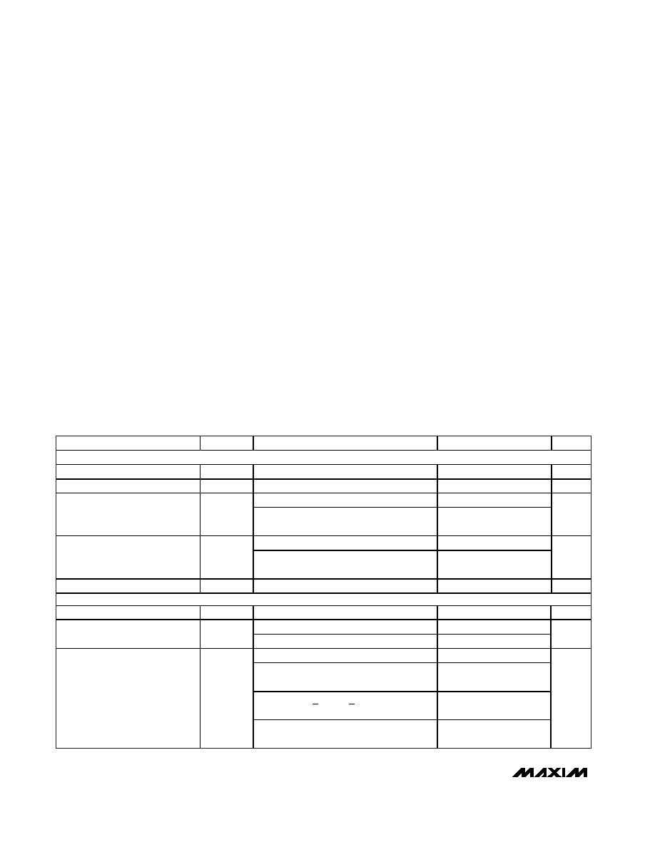
ELECTRICAL CHARACTERISTICS
(VCC = +9.75V, VEE = -5.25V, VCCO_ = +2.5V, SC1 = SC0 = 0, VCPHV_ = +7.2V, VCPLV_ = -2.2V, VLDH_ = VLDL_ = 0, VGS = 0,
TJ = +85
°C, unless otherwise noted. All temperature coefficients are measured at TJ = +70°C to +100°C, unless otherwise noted.) (Note 1)
Stresses beyond those listed under “Absolute Maximum Ratings” may cause permanent damage to the device. These are stress ratings only, and functional
operation of the device at these or any other conditions beyond those indicated in the operational sections of the specifications is not implied. Exposure to
absolute maximum rating conditions for extended periods may affect device reliability.
VCC to GND .........................................................-0.3V to +11.5V
VEE to GND............................................................-7.0V to +0.3V
VCC - VEE................................................................-0.3V to +18V
GS to GND ...........................................................……………
±1V
DUT_, LDH_, LDL_ to GND ...................................-2.5V to +7.5V
DATA_, NDATA_, RCV_, NRCV_,
LDEN_, NLDEN_ to GND ...............................…-2.5V to +5.0V
DATA_ to NDATA_, RCV_ to NRCV_,
LDEN_ to NLDEN_............................................…………±1.5V
VCCO_ to GND ..........................................................-0.3V to +5V
SCLK, DIN, CS, RST, TDATA_,
TRCV_, TLDEN_ to GND ..................................…-1.0V to +5V
DHV_, DLV_, DTV_, CHV_, CLV_, COM_,
FORCE_, SENSE_ to GND.................................-2.5V to +7.5V
CPHV_ to GND ......................................................-2.5V to +8.5V
CPLV_ to GND.......................................................-3.5V to +7.5V
DHV_ to DLV_........................................................…………±10V
DHV_ to DTV_........................................................…………±10V
DLV_ to DTV_ ........................................................…………±10V
CHV_ or CLV_ to DUT_..........................................…………±10V
CH_, NCH_, CL_, NCL_ to GND (open collector) ....-2.5V to +5V
CH_, NCH_, CL_, NCL_ to GND (open emitter) ..(VCCO_ + 1.0V)
All Other Pins to GND ......................(VEE - 0.3V) to (VCC + 0.3V)
Current Out of CH_, NCH_, CL_, NCL_ (open emitter) ....+50mA
DHV_, DLV_, DTV_, CHV_, CLV_,
CPHV_, CPLV_ Current.....................................……….±10mA
TEMP Current...................................................-0.5mA to +20mA
DUT_ Short Circuit to -1.5V to +6.5V..........................Continuous
Power Dissipation (TA = +70°C)
MAX9967_ _CCQ (derate 167mW/°C above +70°C) ....13.3W*
Storage Temperature Range .............................-65°C to +150°C
Junction Temperature ......................................................+125°C
Lead Temperature (soldering, 10s) ....................………..+300°C
PARAMETER
SYMBOL
CONDITIONS
MIN
TYP
MAX
UNITS
POWER SUPPLIES
Positive Supply
VCC
9.5
9.75
10.5
V
Negative Supply
VEE
-6.5
-5.25
-4.5
V
VLDH_ = VLDL_ = 0
120
155
Positive Supply Current
(Note 2)
ICC
VLDH_ = VLDL_ = 3.5V, load enabled,
driver = high impedance
220
255
mA
VLDH_ = VLDL_ = 0
-220
-265
Negative Supply Current
(Note 2)
IEE
VLDH_ = VLDL_ = 3.5V, load enabled,
driver = high impedance
-320
-365
mA
Power Dissipation
PD
(Notes 2, 3)
2.3
2.9
W
DUT_ CHARACTERISTICS
Operating Voltage Range
VDUT
(Note 4)
-1.5
+6.5
V
LLEAK = 0; 0
≤ VDUT_ ≤ 3V
±1.5
Leakage Current in High-
Impedance Mode
IDUT
LLEAK = 0; VDUT_ = -1.5V, +6.5V
±3
A
LLEAK = 1; 0
≤ VDUT_ ≤ 3V, TJ < +90°C
±60
LLEAK = 1; VDUT_ = -1.5V, +6.5V;
TJ < +90
°C
±110
LLEAK = 1; 0 < VDUT_ < 3V, VLDL_=
VLDH_ = 3.5V; TJ < +90
°C
±80
Leakage Current in Low-Leakage
Mode
LLEAK = 1; VDUT_ = -1.5V, +6.5V;
VLDL_ = VLDH_ = 3.5V; TJ < +90
°C
±160
nA
*Dissipation wattage values are based on still air with no heat sink. Actual maximum allowable power dissipation is a function of heat
extraction technique and may be substantially higher.
相關(guān)PDF資料 |
PDF描述 |
|---|---|
| MS27497E24F29P | CONN RCPT 29POS WALL MNT W/PINS |
| D38999/26FJ43PN | CONN PLUG 43POS STRAIGHT W/PINS |
| MS3116P20-41P | CONN PLUG 41POS STRAIGHT W/PINS |
| MAX9967BRCCQ+D | IC DCL DUAL 500MBPS ATE 100TQFP |
| MAX1224CTC+ | IC ADC 12BIT 1.5MSPS 12-TQFN |
相關(guān)代理商/技術(shù)參數(shù) |
參數(shù)描述 |
|---|---|
| MAX9967ALCCQ | 制造商:Rochester Electronics LLC 功能描述: 制造商:Maxim Integrated Products 功能描述: |
| MAX9967ALCCQ+D | 功能描述:緩沖器和線路驅(qū)動器 RoHS:否 制造商:Micrel 輸入線路數(shù)量:1 輸出線路數(shù)量:2 極性:Non-Inverting 電源電壓-最大:+/- 5.5 V 電源電壓-最小:+/- 2.37 V 最大工作溫度:+ 85 C 安裝風(fēng)格:SMD/SMT 封裝 / 箱體:MSOP-8 封裝:Reel |
| MAX9967ALCCQ+TD | 功能描述:緩沖器和線路驅(qū)動器 RoHS:否 制造商:Micrel 輸入線路數(shù)量:1 輸出線路數(shù)量:2 極性:Non-Inverting 電源電壓-最大:+/- 5.5 V 電源電壓-最小:+/- 2.37 V 最大工作溫度:+ 85 C 安裝風(fēng)格:SMD/SMT 封裝 / 箱體:MSOP-8 封裝:Reel |
| MAX9967ALCCQ-D | 功能描述:緩沖器和線路驅(qū)動器 RoHS:否 制造商:Micrel 輸入線路數(shù)量:1 輸出線路數(shù)量:2 極性:Non-Inverting 電源電壓-最大:+/- 5.5 V 電源電壓-最小:+/- 2.37 V 最大工作溫度:+ 85 C 安裝風(fēng)格:SMD/SMT 封裝 / 箱體:MSOP-8 封裝:Reel |
| MAX9967ALCCQ-TD | 功能描述:緩沖器和線路驅(qū)動器 RoHS:否 制造商:Micrel 輸入線路數(shù)量:1 輸出線路數(shù)量:2 極性:Non-Inverting 電源電壓-最大:+/- 5.5 V 電源電壓-最小:+/- 2.37 V 最大工作溫度:+ 85 C 安裝風(fēng)格:SMD/SMT 封裝 / 箱體:MSOP-8 封裝:Reel |
發(fā)布緊急采購,3分鐘左右您將得到回復(fù)。