- 您現(xiàn)在的位置:買(mǎi)賣(mài)IC網(wǎng) > Datasheet目錄43 > MAX4370ESA+T (Maxim Integrated)IC CNTRLR HOT-SWAP 8-SOIC Datasheet資料下載
參數(shù)資料
| 型號(hào): | MAX4370ESA+T |
| 廠商: | Maxim Integrated |
| 文件頁(yè)數(shù): | 12/16頁(yè) |
| 文件大小: | 432K |
| 描述: | IC CNTRLR HOT-SWAP 8-SOIC |
| 產(chǎn)品培訓(xùn)模塊: | Lead (SnPb) Finish for COTS Obsolescence Mitigation Program |
| 標(biāo)準(zhǔn)包裝: | 2,500 |
| 類(lèi)型: | 熱交換控制器 |
| 應(yīng)用: | 通用 |
| 內(nèi)部開(kāi)關(guān): | 無(wú) |
| 電源電壓: | 2.7 V ~ 13.2 V |
| 工作溫度: | -40°C ~ 85°C |
| 安裝類(lèi)型: | 表面貼裝 |
| 封裝/外殼: | 8-SOIC(0.154",3.90mm 寬) |
| 供應(yīng)商設(shè)備封裝: | 8-SOIC |
| 包裝: | 帶卷 (TR) |
第1頁(yè)第2頁(yè)第3頁(yè)第4頁(yè)第5頁(yè)第6頁(yè)第7頁(yè)第8頁(yè)第9頁(yè)第10頁(yè)第11頁(yè)當(dāng)前第12頁(yè)第13頁(yè)第14頁(yè)第15頁(yè)第16頁(yè)

Current-Regulating Hot-Swap Controller with
DualSpeed/BiLevel Fault Protection
12 ______________________________________________________________________________________
Case A: Slow Turn-On (without overcurrent)
There are two ways to turn on the MOSFET without
reaching the fast comparator current limit:
1) If the board capacitance (C
BOARD
) is low, the
inrush current is low.
2) If the capacitance at GATE is high, the MOSFET
turns on slowly.
In both cases, the turn-on (t
ON
) is determined only by
the charge required to enhance the MOSFETeffec -
tively, the small gate-charging current limits the output
voltage dv/dt. This time can be extended by connect-
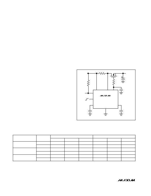
ing an external capacitor between GATE and GND, as
shown in Figure 7. The turn-on time is dominated by the
external gate capacitance if its value is considerably
higher than MOSFET gate capacitance. Table 4 shows
the timing required to enhance the recommended
MOSFET with or without an external capacitor at GATE;
Figures 2 and 3 show the related waveforms and timing
diagrams (see Start-Up Time with C
BOARD
= 0 and
Start-Up Time with External C
GATE
in the Typical
Operating Characteristics). Remember that a high gate
capacitance also increases the turn-off time.
When using the MAX4370 without an external gate
capacitor, R
S
is not necessary. R
S
prevents MOSFET
source oscillations that can occur when C
GATE
is high
while C
BOARD
is low.
Case B: Fast Turn-On (with current limit)
In applications where the board capacitor (C
BOARD
) at
V
OUT
is high, the inrush current causes a voltage drop
across R
SENSE
that exceeds the fast comparator
threshold (V
FC,TH
= 200mV). In this case, the current
charging C
BOARD
can be considered constant and the
turn-on time is determined by:
t
ON
= C
BOARD
?SPAN class="pst MAX4370ESA-T_2342621_3"> V
IN
/ I
FAST,SET
where the maximum load current I
FAST,SET
= V
FC,TH
/
R
SENSE
. Figure 2 shows the waveforms and timing dia-
grams for a turn-on transient with current regulation (see
Start-Up Time with C
BOARD
= 470礔 in the Typical
Operating Characteristics). When operating under this
condition, an external gate capacitor is not required.
Adding an external capacitor at GATE reduces the regu-
lated current ripple but increases the turn-off time by
increasing the gate delay (t
d
) (Figure 3).
M1
C
SPD
*OPTIONAL (SEE TEXT)
C
TIM
CTIM
GATE
VSEN
GND
CSPD
ON
R
SENSE
V
OUT
C
GATE
C
BOARD
V
IN
V
IN
R
S*
MAX4370
R
PULL-UP
STAT
Figure 7. Operation with External Gate Capacitor
Table 4. MOSFET Turn-On Time (start-up without current limit)
(C
BOARD
= 0, turn-on with no load current, turn-off with 2A fault current)
International Rectifier
IRF7401
Fairchild FDS6670A
0
22
0
175祍
1.9ms
220祍
130祍
1.8ms
160祍
160祍
3.5ms
MOSFET TURN-ON (t
ON
)
190祍
75祍
540祍
70祍
130祍
1.1ms
130祍
160祍
2ms
MOSFET TURN-OFF (t
OFF
)
145祍
22
2.3ms
2ms
3.2ms
540祍
1.1ms
1.95ms
0
22
101祍
2ms
74祍
1.8ms
Motorola
MMSF5N03HD
73祍
3.2ms
33祍
470祍
67祍
1ms
85祍
1.95ms
C
GATE
(nF)
V
IN
= 3V
V
IN
= 5V
V
IN
= 12V
V
IN
= 3V
V
IN
= 5V
V
IN
= 12V
DEVICE
Electrical characteristics as specified by the manufacturers data sheet:
FDS6670A: C
ISS
= 3200pF, Q
T(MAX)
= 50nC, R
DS(ON)
= 8.2m&
IRF7401: C
ISS
= 1600pF, Q
T(MAX)
= 48nC, R
DS(ON)
= 22m&
MMSF5N03HD: C
ISS
= 1200pF, Q
T(MAX)
= 21nC, R
DS(ON)
= 40m&
相關(guān)PDF資料 |
PDF描述 |
|---|---|
| MAX4995AFAVB+ | IC CURRENT SWITCH 10% 10UTQFN |
| MAX5900AAEUT+T | IC HOT-SWAP CONTROLLER SOT23-6 |
| MAX5903LAETT+T | IC HOT-SWAP CONTROLLER 6-TDFN |
| MAX5909EEE+ | IC HOT-SWAP CTRLR DUAL 16QSOP |
| MAX5911ESA | IC SW HOTSWAP -48V SWAPPER 8SOIC |
相關(guān)代理商/技術(shù)參數(shù) |
參數(shù)描述 |
|---|---|
| MAX4372FEBT | 制造商:Maxim Integrated Products 功能描述:UCSP/SOT23, MICROPOWER, HIGH-SIDE CURRENT-SENSE AMP - Rail/Tube |
| MAX4372FEBT+ | 制造商:Maxim Integrated Products 功能描述:- Rail/Tube |
| MAX4372FEBT+T | 功能描述:特殊用途放大器 uPower High-Side Current-Sense Amp RoHS:否 制造商:Texas Instruments 通道數(shù)量:Single 共模抑制比(最小值): 輸入補(bǔ)償電壓: 工作電源電壓:3 V to 5.5 V 電源電流:5 mA 最大功率耗散: 最大工作溫度:+ 70 C 最小工作溫度:- 40 C 安裝風(fēng)格:SMD/SMT 封裝 / 箱體:QFN-20 封裝:Reel |
| MAX4372FEBT+TG45 | 功能描述:特殊用途放大器 Low-Cost UCSP/SOT23 Micropower High-Side Current-Sense Amplifier with Voltage Output RoHS:否 制造商:Texas Instruments 通道數(shù)量:Single 共模抑制比(最小值): 輸入補(bǔ)償電壓: 工作電源電壓:3 V to 5.5 V 電源電流:5 mA 最大功率耗散: 最大工作溫度:+ 70 C 最小工作溫度:- 40 C 安裝風(fēng)格:SMD/SMT 封裝 / 箱體:QFN-20 封裝:Reel |
| MAX4372FEBT-T | 功能描述:特殊用途放大器 RoHS:否 制造商:Texas Instruments 通道數(shù)量:Single 共模抑制比(最小值): 輸入補(bǔ)償電壓: 工作電源電壓:3 V to 5.5 V 電源電流:5 mA 最大功率耗散: 最大工作溫度:+ 70 C 最小工作溫度:- 40 C 安裝風(fēng)格:SMD/SMT 封裝 / 箱體:QFN-20 封裝:Reel |
發(fā)布緊急采購(gòu),3分鐘左右您將得到回復(fù)。