- 您現(xiàn)在的位置:買賣IC網 > PDF目錄45053 > M8803F2W-15T1 (STMICROELECTRONICS) 1M X 1 FLASH, 27 I/O, PIA-GENERAL PURPOSE, PQFP52 PDF資料下載
參數(shù)資料
| 型號: | M8803F2W-15T1 |
| 廠商: | STMICROELECTRONICS |
| 元件分類: | 微控制器/微處理器 |
| 英文描述: | 1M X 1 FLASH, 27 I/O, PIA-GENERAL PURPOSE, PQFP52 |
| 封裝: | PLASTIC, QFP-52 |
| 文件頁數(shù): | 18/85頁 |
| 文件大小: | 601K |
| 代理商: | M8803F2W-15T1 |
第1頁第2頁第3頁第4頁第5頁第6頁第7頁第8頁第9頁第10頁第11頁第12頁第13頁第14頁第15頁第16頁第17頁當前第18頁第19頁第20頁第21頁第22頁第23頁第24頁第25頁第26頁第27頁第28頁第29頁第30頁第31頁第32頁第33頁第34頁第35頁第36頁第37頁第38頁第39頁第40頁第41頁第42頁第43頁第44頁第45頁第46頁第47頁第48頁第49頁第50頁第51頁第52頁第53頁第54頁第55頁第56頁第57頁第58頁第59頁第60頁第61頁第62頁第63頁第64頁第65頁第66頁第67頁第68頁第69頁第70頁第71頁第72頁第73頁第74頁第75頁第76頁第77頁第78頁第79頁第80頁第81頁第82頁第83頁第84頁第85頁

25/85
M88 FAMILY
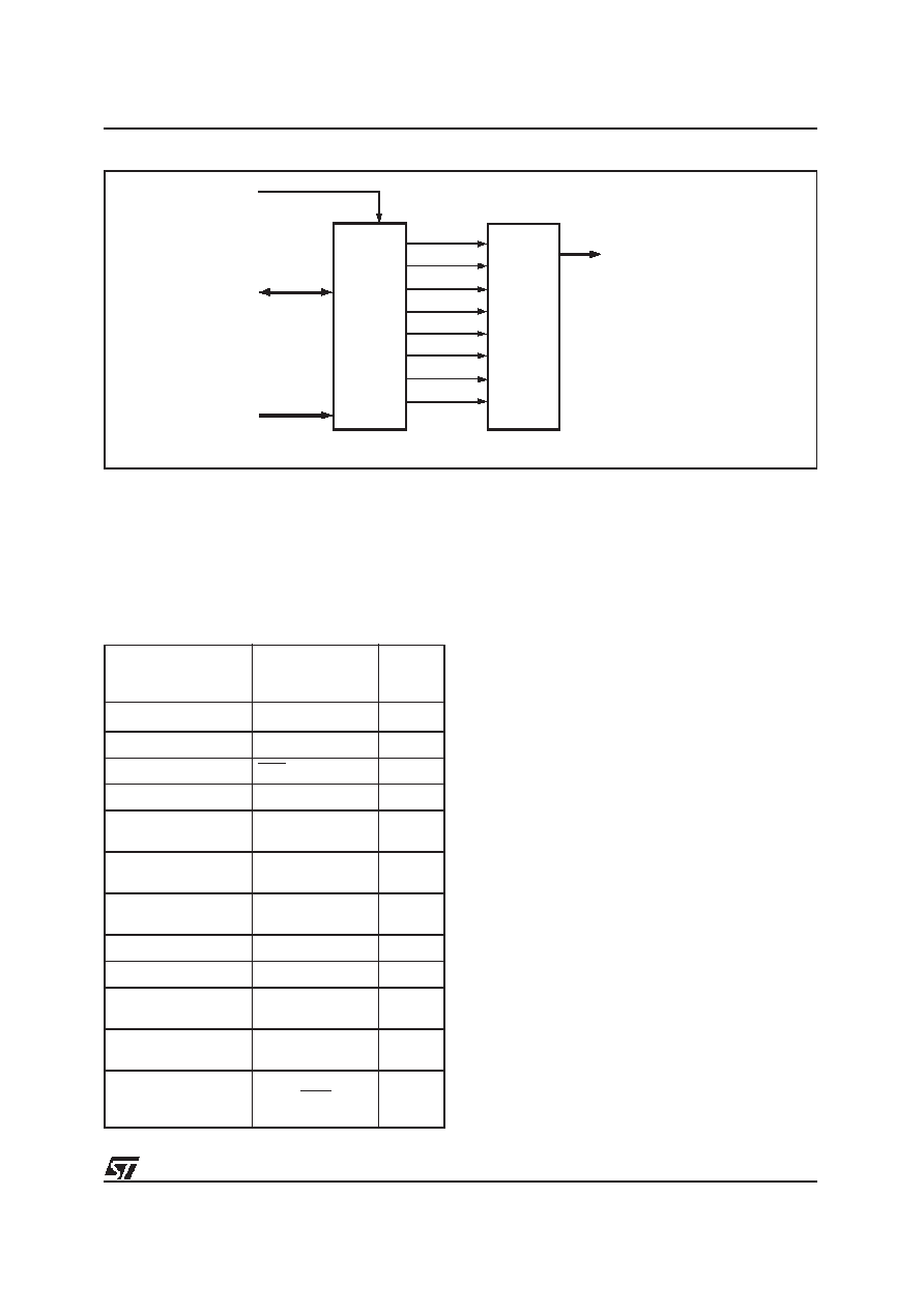
Figu re 13. Page Register
RESET
D0 - D7
R/ W
D0
Q0
Q1
Q2
Q3
Q4
Q5
Q6
Q7
D1
D2
D3
D4
D5
D6
D7
PAGE
REGISTER
PGR0
PGR1
PGR2
PGR3
FLASH
DPLD
AND
FLASH
CPLD
INTERNAL
SELECTS
AND LOGIC
FLASH
PLD
PGR4
PGR5
PGR6
PGR7
AI02871
Decode PLD (DPLD)
The DPLD, shown in Figure 15, is used for
decoding the address for internal and external
components.
The
DPLD
can
generate
the
following decode signals:
s
8 sector selects for the main Flash memory
(three product terms each)
s
4 sector selects for the optional EEPROM or
Flash Boot memory (three product terms each)
s
1 internal SRAM select signal (two product
terms)
s
1 internal CSIOP (PSD configuration register)
select signal
s
1 JTAG select signal (enables JTAG on Port C)
s
2 internal peripheral select signals
(peripheral I/O mode).
Complex PLD (CPLD)
The CPLD can be used to implement system logic
functions, such as loadable counters and shift
registers,
syst em
mailboxes,
handshaking
protocols, state machines, and random logic. The
CPLD can also be used to generate 3 external
chip selects, routed to Port D.
Although external chip selects can be produced by
any Output Macrocell, these three external chip
selects on Port D do not consume any Output
Macrocells.
As shown in Figure 14, the CPLD has the following
blocks:
s
24 Input Macrocells (IMCs)
s
16 Output Macrocells (OMCs)
s
Macrocell Allocator
s
Product Term Allocator
s
AND array capable of generating up to 140
product terms
s
Four I/O ports.
Table 17. DPLD and CPLD Inpu ts
Note: 1. The address inputs are A[19:4] in 80C51XA mode.
Input Source
Input Name
Number
of
Sign als
MCU Address Bus1
A[15:0]
16
MCU Control Signals
CNTL[2:0]
3
Reset
RST
1
Power Down
PDN
1
Port A Input
Macrocells
PA[7-0]
8
Port B Input
Macrocells
PB[7-0]
8
Port C Input
Macrocells
PC[7-0]
8
Port D Inputs
PD[2:0]
3
Page Register
PGR(7:0)
8
Macrocell AB
Feedback
MCELLAB.FB[7:0]
8
Macrocell BC
Feedback
MCELLBC.FB[7:0]
8
EEPROM/Boot Flash
Programming Status
Bit
Ready/Busy
1
相關PDF資料 |
PDF描述 |
|---|---|
| M8813F3W-15K1 | 1M X 1 FLASH, 27 I/O, PIA-GENERAL PURPOSE, PQCC52 |
| M8813F3Y-90K1 | 1M X 1 FLASH, 27 I/O, PIA-GENERAL PURPOSE, PQCC52 |
| M8813F3Y-90T1 | 1M X 1 FLASH, 27 I/O, PIA-GENERAL PURPOSE, PQFP52 |
| M8803F3Y-90K1T | 1M X 1 FLASH, 27 I/O, PIA-GENERAL PURPOSE, PQCC52 |
| M8813F3Y-90K1T | 1M X 1 FLASH, 27 I/O, PIA-GENERAL PURPOSE, PQCC52 |
相關代理商/技術參數(shù) |
參數(shù)描述 |
|---|---|
| M8805/100-007 | 制造商:OTTO Engineering Inc 功能描述:M8805/100-007 |
| M8805/100-009 | 制造商:OTTO Engineering Inc 功能描述:M8805/100-009 |
| M8805/100-010 | 制造商:OTTO Engineering Inc 功能描述:M8805/100-010 |
| M8805/100-015 | 制造商:OTTO Engineering Inc 功能描述:M8805/100-015 |
| M8805/100-016 | 制造商:OTTO Engineering Inc 功能描述:M8805/100-016 |
發(fā)布緊急采購,3分鐘左右您將得到回復。