- 您現(xiàn)在的位置:買賣IC網(wǎng) > PDF目錄69011 > M34584MD-XXXFP 4-BIT, MROM, 6 MHz, MICROCONTROLLER, PDSO42 PDF資料下載
參數(shù)資料
| 型號: | M34584MD-XXXFP |
| 元件分類: | 微控制器/微處理器 |
| 英文描述: | 4-BIT, MROM, 6 MHz, MICROCONTROLLER, PDSO42 |
| 封裝: | 0.450 INCH, 0.80 MM PITCH, PLASTIC, SSOP-42 |
| 文件頁數(shù): | 131/159頁 |
| 文件大?。?/td> | 1166K |
| 代理商: | M34584MD-XXXFP |
第1頁第2頁第3頁第4頁第5頁第6頁第7頁第8頁第9頁第10頁第11頁第12頁第13頁第14頁第15頁第16頁第17頁第18頁第19頁第20頁第21頁第22頁第23頁第24頁第25頁第26頁第27頁第28頁第29頁第30頁第31頁第32頁第33頁第34頁第35頁第36頁第37頁第38頁第39頁第40頁第41頁第42頁第43頁第44頁第45頁第46頁第47頁第48頁第49頁第50頁第51頁第52頁第53頁第54頁第55頁第56頁第57頁第58頁第59頁第60頁第61頁第62頁第63頁第64頁第65頁第66頁第67頁第68頁第69頁第70頁第71頁第72頁第73頁第74頁第75頁第76頁第77頁第78頁第79頁第80頁第81頁第82頁第83頁第84頁第85頁第86頁第87頁第88頁第89頁第90頁第91頁第92頁第93頁第94頁第95頁第96頁第97頁第98頁第99頁第100頁第101頁第102頁第103頁第104頁第105頁第106頁第107頁第108頁第109頁第110頁第111頁第112頁第113頁第114頁第115頁第116頁第117頁第118頁第119頁第120頁第121頁第122頁第123頁第124頁第125頁第126頁第127頁第128頁第129頁第130頁當前第131頁第132頁第133頁第134頁第135頁第136頁第137頁第138頁第139頁第140頁第141頁第142頁第143頁第144頁第145頁第146頁第147頁第148頁第149頁第150頁第151頁第152頁第153頁第154頁第155頁第156頁第157頁第158頁第159頁
Rev.3.00
2004.08.06
page 71 of 155
REJ03B0010-0300Z
4584 Group
PRELIMINARY
Notice: This is not a final specification.
Some parametric limits are subject to change.
POF instruction
When the POF instruction is executed continuously after the
EPOF instruction, system enters the RAM back-up state.
Note that system cannot enter the RAM back-up state when ex-
ecuting only the POF instruction.
Be sure to disable interrupts by executing the DI instruction be-
fore executing the EPOF instruction and the POF instruction
continuously.
Program counter
Make sure that the PC does not specify after the last page of the
built-in ROM.
Power-on reset
When the built-in power-on reset circuit is used, the time for the
supply voltage to rise from 0 V to the value of supply voltage or
more must be set to 100
s or less. If the rising time exceeds 100
s, connect a capacitor between the RESET pin and VSS at the
shortest distance, and input “L” level to RESET pin until the value
of supply voltage reaches the minimum operating voltage.
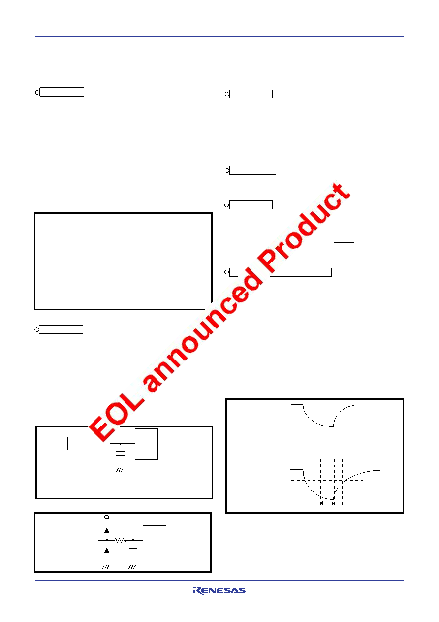
Note on voltage drop detection circuit
The voltage drop detection circuit detection voltage of this prod-
uct is set up lower than the minimum value of the supply voltage
of the recommended operating conditions.
When the supply voltage of a microcomputer falls below to the
minimum value of recommended operating conditions and re-
goes up (ex. battery exchange of an application product),
depending on the capacity value of the bypass capacitor added
to the power supply pin, the following case may cause program
failure (Figure 68);
supply voltage does not fall below to VRST-, and
its voltage re-goes up with no reset.
In such a case, please design a system which supply voltage is
once reduced below to VRST- and re-goes up after that.
19
21
A/D converter-1
When the TALA instruction is executed, the low-order 2 bits of
register AD is transferred to the high-order 2 bits of register A, si-
multaneously, the low-order 2 bits of register A is “0.”
Do not change the operating mode (both A/D conversion mode
and comparator mode) of A/D converter with the bit 3 of register
Q1 while the A/D converter is operating.
Clear the bit 2 of register V2 to “ 0”
to change the operating mode of
the A/D converter from the comparator mode to A/D conversion mode.
The A/D conversion completion flag (ADF) may be set when the
operating mode of the A/D converter is changed from the com-
parator mode to the A/D conversion mode. Accordingly, set a
value to the register Q1, and execute the SNZAD instruction to
clear the ADF flag.
LA
8
; (02)
TV2A
; The SNZAD instruction is valid ........
LA
0
; (02)
TQ1A
; Operation mode of A/D converter is
changed from comparator mode to A/D
conversion mode.
SNZAD
NOP
: these bits are not used here.
Fig. 65 A/D converter program example-3
Fig. 66 Analog input external circuit example-1
A/D converter-2
Each analog input pin is equipped with a capacitor which is used
to compare the analog voltage. Accordingly, when the analog volt-
age is input from the circuit with high-impedance and, charge/
discharge noise is generated and the sufficient A/D accuracy may
not be obtained. Therefore, reduce the impedance or, connect a
capacitor (0.01
F to 1 F) to analog input pins (Figure 66).
When the overvoltage applied to the A/D conversion circuit may
occur, connect an external circuit in order to keep the voltage
within the rated range as shown the Figure 67. In addition, test
the application products sufficiently.
17
18
Fig. 67 Analog input external circuit example-2
20
Fig. 68 VDD and VRST–
VDD
Recommended
operatng condition
min.value
No reset
Program failure may occur.
VRST
+
VRST
–
VDD
Recommended
operatng condition
min.value
VRST
+
VRST
–
→ Normal operation
Reset
22
Sensor
AIN
Apply the voltage withiin the specifications
to an analog input pin.
Sensor
AIN
About 1k
相關PDF資料 |
PDF描述 |
|---|---|
| M35017-001FP | 24 X 10 CHARACTERS CRT CHAR DSPL CTLR, PDSO20 |
| M35040-001FP | 24 X 10 CHARACTERS CRT CHAR DSPL CTLR, PDSO20 |
| M35043-001SP | 24 X 12 CHARACTERS CRT CHAR DSPL CTLR, PDIP20 |
| M35043-001FP | 24 X 12 CHARACTERS CRT CHAR DSPL CTLR, PDSO20 |
| M35045-XXXSP | 24 X 12 CHARACTERS CRT CHAR DSPL CTLR, PDIP20 |
相關代理商/技術參數(shù) |
參數(shù)描述 |
|---|---|
| M3459 | 功能描述:電纜固定件和配件 RLTCG 3/8 NPT GRAY NO NUT RoHS:否 制造商:Heyco 類型:Cable Grips, Liquid Tight 材料:Nylon 顏色:Black 安裝方法:Cable 最大光束直徑:11.4 mm 抗拉強度: |
| M3460 | 功能描述:電纜固定件和配件 RLTCG 3/4 NPT BLACK NO NUT RoHS:否 制造商:Heyco 類型:Cable Grips, Liquid Tight 材料:Nylon 顏色:Black 安裝方法:Cable 最大光束直徑:11.4 mm 抗拉強度: |
| M3460-3R9-083 | 制造商:Bonitron 功能描述:REGULATOR FOR VFDS |
| M3460B-E130-R2-DDM-P3 | 制造商:Bonitron 功能描述:UNDERVOLTAGE RIDE-THRU PRODUCT |
| M3460D-2L-60 | 制造商:Bonitron 功能描述:UNDERVOLTAGE RIDE-THRU PRODUCT |
發(fā)布緊急采購,3分鐘左右您將得到回復。