- 您現(xiàn)在的位置:買賣IC網(wǎng) > PDF目錄67761 > M34502M2-XXXFP 4-BIT, MROM, MICROCONTROLLER, PDSO24 PDF資料下載
參數(shù)資料
| 型號: | M34502M2-XXXFP |
| 元件分類: | 微控制器/微處理器 |
| 英文描述: | 4-BIT, MROM, MICROCONTROLLER, PDSO24 |
| 封裝: | 5.30 X 10.10 MM, 0.80 MM PITCH, PLASTIC, SSOP-24 |
| 文件頁數(shù): | 93/116頁 |
| 文件大?。?/td> | 896K |
| 代理商: | M34502M2-XXXFP |
第1頁第2頁第3頁第4頁第5頁第6頁第7頁第8頁第9頁第10頁第11頁第12頁第13頁第14頁第15頁第16頁第17頁第18頁第19頁第20頁第21頁第22頁第23頁第24頁第25頁第26頁第27頁第28頁第29頁第30頁第31頁第32頁第33頁第34頁第35頁第36頁第37頁第38頁第39頁第40頁第41頁第42頁第43頁第44頁第45頁第46頁第47頁第48頁第49頁第50頁第51頁第52頁第53頁第54頁第55頁第56頁第57頁第58頁第59頁第60頁第61頁第62頁第63頁第64頁第65頁第66頁第67頁第68頁第69頁第70頁第71頁第72頁第73頁第74頁第75頁第76頁第77頁第78頁第79頁第80頁第81頁第82頁第83頁第84頁第85頁第86頁第87頁第88頁第89頁第90頁第91頁第92頁當(dāng)前第93頁第94頁第95頁第96頁第97頁第98頁第99頁第100頁第101頁第102頁第103頁第104頁第105頁第106頁第107頁第108頁第109頁第110頁第111頁第112頁第113頁第114頁第115頁第116頁
Skip condition
Number of
cycles
Number of
words
Instruction
code
D9
D0
Flag CY
2
16
Skip condition
Number of
cycles
Number of
words
Instruction
code
D9
D0
Flag CY
2
16
Skip condition
Number of
cycles
Number of
words
Instruction
code
D9
D0
Flag CY
2
16
Skip condition
Number of
cycles
Number of
words
Instruction
code
D9
D0
Flag CY
2
16
Rev.3.01
2005.02.02
page 78 of 112
REJ03B0105-0301
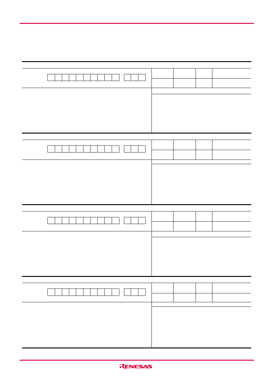
4502 Group
TABE (Transfer data to Accumulator and register B from register E)
0000101010
02A
11
–
Grouping:
Register to register transfer
Description: Transfers the high-order 4 bits (E7–E4) of
register E to register B, and low-order 4 bits
of register E to register A.
Operation:
(B)
← (E7–E4)
(A)
← (E3–E0)
TABP p (Transfer data to Accumulator and register B from Program memory in page p)
00100p4
p3
p2
p1
p0
0p
13
–
Grouping:
Arithmetic operation
Description: Transfers bits 7 to 4 to register B and bits 3 to
0 to register A. These bits 7 to 0 are the ROM
pattern in ad-dress (DR2 DR1 DR0 A3 A2 A1
A0)2 specified by registers A and D in page p.
Note:
p is 0 to 15 for M34502M2, and p is 0 to 31
for M34502M4/E4.
When this instruction is executed, be careful
not to over the stack because 1 stage of
stack register is used.
Operation:
(SP)
← (SP) + 1
(SK(SP))
← (PC)
(PCH)
← p
(PCL)
← (DR2–DR0, A3–A0)
(B)
← (ROM(PC))7–4
(A)
← (ROM(PC))3–0
(PC)
← (SK(SP))
(SP)
← (SP) – 1
TAD (Transfer data to Accumulator from register D)
0001010001
051
11
–
Grouping:
Register to register transfer
Description: Transfers the contents of register D to the
low-order 3 bits (A2–A0) of register A.
Note:
When this instruction is executed, “0” is
stored to the bit 3 (A3) of register A.
TADAB (Transfer data to register AD from Accumulator from register B)
1000111001
239
11
–
Grouping:
A/D conversion operation
Description: In the A/D conversion mode (Q13 = 0), this in-
struction is equivalent to the NOP instruction.
In the comparator mode (Q13 = 1), trans-
fers the contents of register B to the
high-order 4 bits (AD7–AD4) of comparator
register, and the contents of register A to
the low-order 4 bits (AD3–AD0) of compara-
tor register.
(Q13 = bit 3 of A/D control register Q1)
Operation:
(AD7–AD4)
← (B)
(AD3–AD0)
← (A)
Operation:
(A2–A0)
← (DR2–DR0)
(A3)
← 0
8
+p
MACHINE INSTRUCTIONS (INDEX BY ALPHABET) (continued)
相關(guān)PDF資料 |
PDF描述 |
|---|---|
| M34508G4GP | 4-BIT, MROM, 6 MHz, MICROCONTROLLER, PDSO20 |
| M34508G4H-XXXFP | 4-BIT, MROM, 6 MHz, MICROCONTROLLER, PDSO20 |
| M34508G4-XXXFP | 4-BIT, MROM, 6 MHz, MICROCONTROLLER, PDSO20 |
| M34508G4HGP | 4-BIT, MROM, 6 MHz, MICROCONTROLLER, PDSO20 |
| M34508G4FP | 4-BIT, MROM, 6 MHz, MICROCONTROLLER, PDSO20 |
相關(guān)代理商/技術(shù)參數(shù) |
參數(shù)描述 |
|---|---|
| M34502M4 | 制造商:RENESAS 制造商全稱:Renesas Technology Corp 功能描述:SINGLE-CHIP 4-BIT CMOS MICROCOMPUTER |
| M34502M4-XXXFP | 制造商:RENESAS 制造商全稱:Renesas Technology Corp 功能描述:SINGLE-CHIP 4-BIT CMOS MICROCOMPUTER |
| M34506E4 | 制造商:RENESAS 制造商全稱:Renesas Technology Corp 功能描述:SINGLE-CHIP 4-BIT CMOS MICROCOMPUTER |
| M34506E4FP | 制造商:RENESAS 制造商全稱:Renesas Technology Corp 功能描述:SINGLE-CHIP 4-BIT CMOS MICROCOMPUTER |
| M34506M2 | 制造商:RENESAS 制造商全稱:Renesas Technology Corp 功能描述:SINGLE-CHIP 4-BIT CMOS MICROCOMPUTER |
發(fā)布緊急采購,3分鐘左右您將得到回復(fù)。