- 您現(xiàn)在的位置:買賣IC網(wǎng) > PDF目錄69008 > M30218MC-XXXXFP 16-BIT, MROM, 10 MHz, MICROCONTROLLER, PQFP100 PDF資料下載
參數(shù)資料
| 型號: | M30218MC-XXXXFP |
| 元件分類: | 微控制器/微處理器 |
| 英文描述: | 16-BIT, MROM, 10 MHz, MICROCONTROLLER, PQFP100 |
| 封裝: | PLASTIC, QFP-100 |
| 文件頁數(shù): | 139/161頁 |
| 文件大?。?/td> | 2043K |
| 代理商: | M30218MC-XXXXFP |
第1頁第2頁第3頁第4頁第5頁第6頁第7頁第8頁第9頁第10頁第11頁第12頁第13頁第14頁第15頁第16頁第17頁第18頁第19頁第20頁第21頁第22頁第23頁第24頁第25頁第26頁第27頁第28頁第29頁第30頁第31頁第32頁第33頁第34頁第35頁第36頁第37頁第38頁第39頁第40頁第41頁第42頁第43頁第44頁第45頁第46頁第47頁第48頁第49頁第50頁第51頁第52頁第53頁第54頁第55頁第56頁第57頁第58頁第59頁第60頁第61頁第62頁第63頁第64頁第65頁第66頁第67頁第68頁第69頁第70頁第71頁第72頁第73頁第74頁第75頁第76頁第77頁第78頁第79頁第80頁第81頁第82頁第83頁第84頁第85頁第86頁第87頁第88頁第89頁第90頁第91頁第92頁第93頁第94頁第95頁第96頁第97頁第98頁第99頁第100頁第101頁第102頁第103頁第104頁第105頁第106頁第107頁第108頁第109頁第110頁第111頁第112頁第113頁第114頁第115頁第116頁第117頁第118頁第119頁第120頁第121頁第122頁第123頁第124頁第125頁第126頁第127頁第128頁第129頁第130頁第131頁第132頁第133頁第134頁第135頁第136頁第137頁第138頁當前第139頁第140頁第141頁第142頁第143頁第144頁第145頁第146頁第147頁第148頁第149頁第150頁第151頁第152頁第153頁第154頁第155頁第156頁第157頁第158頁第159頁第160頁第161頁
79
Under
development
Tentative Specifications REV.A
Specifications in this manual are tentative and subject to change.
Mitsubishi microcomputers
M30218 Group
SINGLE-CHIP 16-BIT CMOS MICROCOMPUTER
TimerA
(4) Pulse width modulation (PWM) mode
In this mode, the timer outputs pulses of a given width in succession. (See Table FB-5.) In this mode, the counter
functions as either a 16-bit pulse width modulator or an 8-bit pulse width modulator. Figure FB-10 shows the
timer Ai mode register in pulse width modulation mode. Figure FB-11 shows the example of how a 16-bit pulse
width modulator operates. Figure FB-12 shows the example of how an 8-bit pulse width modulator operates.
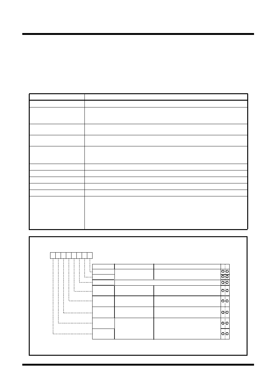
Table FB-5. Timer specifications in pulse width modulation mode
Figure FB-10. Timer Ai mode register in pulse width modulation mode
Item
Specification
Count source
f1, f8, f32, fC32
Count operation
The timer counts down (operating as an 8-bit or a 16-bit pulse width modulator)
The timer reloads a new count at a rising edge of PWM pulse and continues counting
The timer is not affected by a trigger that occurs when counting
16-bit PWM
High level width
n / fi
n : Set value
Cycle time
(216-1) / fi fixed
8-bit PWM
High level width
n X (m+1) / fi
n : values set to timer Ai register’s high-order address
Cycle time
(28-1) X (m+1) / fi
m : values set to timer Ai register’s low-order address
Count start condition
External trigger is input
The timer overflows
The count start flag is set (= 1)
Count stop condition
The count start flag is reset (= 0)
Interrupt request generation timing
PWM pulse goes “L”
TAiIN pin function
Programmable I/O port or trigger input
TAiOUT pin function
Pulse output
Read from timer
When timer Ai register is read, it indicates an indeterminate value
Write to timer
When counting stopped
When a value is written to timer Ai register, it is written to both reload
register and counter
When counting in progress
When a value is written to timer Ai register, it is written to only reload register
(Transferred to counter at next reload time)
Timer Ai mode register
SymbolAddressWhen reset
TAiMR(i=0 to 4)039616 to 039A16
0016
Bit nameFunction
Bit symbol
b7
b6b5b4b3
b2b1b0
Operation mode
select bit
1 1 : PWM mode
b1 b0
TMOD1
TMOD0
MR0
MR2
MR1
MR3
0 0 : f1
0 1 : f8
1 0 : f32
1 1 : fC32
b7 b6
TCK1
TCK0
Count source select bit
W
R
11
1
1 (Must always be fixed to “1” in PWM mode)
16/8-bit PWM mode
select bit
0: Functions as a 16-bit pulse width modulator
1: Functions as an 8-bit pulse width modulator
Trigger select bit
External trigger select
bit (Note 1)
0: Falling edge of TAiIN pin's input signal (Note 2)
1: Rising edge of TAiIN pin's input signal (Note 2)
0: Count start flag is valid
1: Selected by event/trigger select register
Note 1: Valid only when the TAiIN pin is selected by the event/trigger select bit
(addresses 038216 and 038316). If timer overflow is selected, this bit can be “1” or “0
Note 2: Set the corresponding port direction register to “0”.
相關(guān)PDF資料 |
PDF描述 |
|---|---|
| M30218MFCFP | 16-BIT, FLASH, 10 MHz, MICROCONTROLLER, PQFP100 |
| M30220FCRP | 16-BIT, FLASH, 10 MHz, MICROCONTROLLER, PQFP144 |
| M30220MA-XXXGP | 16-BIT, MROM, 10 MHz, MICROCONTROLLER, PQFP144 |
| M30220MA-XXXRP | 16-BIT, MROM, 10 MHz, MICROCONTROLLER, PQFP144 |
| M30220FCRP | 16-BIT, FLASH, 10 MHz, MICROCONTROLLER, PQFP144 |
相關(guān)代理商/技術(shù)參數(shù) |
參數(shù)描述 |
|---|---|
| M3021E8F2-AXXXFP | 制造商:RENESAS 制造商全稱:Renesas Technology Corp 功能描述:SINGLE-CHIP 16-BIT CMOS MICROCOMPUTER |
| M3021E8F4-AXXXFP | 制造商:RENESAS 制造商全稱:Renesas Technology Corp 功能描述:SINGLE-CHIP 16-BIT CMOS MICROCOMPUTER |
| M3021E8F6-AXXXFP | 制造商:RENESAS 制造商全稱:Renesas Technology Corp 功能描述:SINGLE-CHIP 16-BIT CMOS MICROCOMPUTER |
| M3021E8F8-AXXXFP | 制造商:RENESAS 制造商全稱:Renesas Technology Corp 功能描述:SINGLE-CHIP 16-BIT CMOS MICROCOMPUTER |
| M3021E8FA-AXXXFP | 制造商:RENESAS 制造商全稱:Renesas Technology Corp 功能描述:SINGLE-CHIP 16-BIT CMOS MICROCOMPUTER |
發(fā)布緊急采購,3分鐘左右您將得到回復。