- 您現(xiàn)在的位置:買賣IC網(wǎng) > PDF目錄369855 > LTI969CMS Voltage-Feedback Operational Amplifier PDF資料下載
參數(shù)資料
| 型號(hào): | LTI969CMS |
| 英文描述: | Voltage-Feedback Operational Amplifier |
| 中文描述: | 電壓反饋運(yùn)算放大器 |
| 文件頁(yè)數(shù): | 12/20頁(yè) |
| 文件大小: | 285K |
| 代理商: | LTI969CMS |
第1頁(yè)第2頁(yè)第3頁(yè)第4頁(yè)第5頁(yè)第6頁(yè)第7頁(yè)第8頁(yè)第9頁(yè)第10頁(yè)第11頁(yè)當(dāng)前第12頁(yè)第13頁(yè)第14頁(yè)第15頁(yè)第16頁(yè)第17頁(yè)第18頁(yè)第19頁(yè)第20頁(yè)

12
LT1969
Capacitive Loading
The LT1969 is stable with a 1000pF capacitive load. The
photo of the small-signal response with 1000pF load in a
gain of 10 shows 50% overshoot. The photo of the large-
signal response with a 1000pF load shows that the output
slew rate is not limited by the short-circuit current. The
Typical Performance Curve of Frequency Response vs
Capacitive Load shows the peaking for various capacitive
loads.
This stability is useful in the case of directly driving a
coaxial cable or twisted pair that is inadvertently
unterminated. For best pulse fidelity, however, a termina-
tion resistor of value equal to the characteristic impedance
of the cable or twisted pair (i.e., 50
/75
/100
/135
)
should be placed in series with the output. The other end
of the cable or twisted pair should be terminated with the
same value resistor to ground.
APPLICATIOU
W
U
U
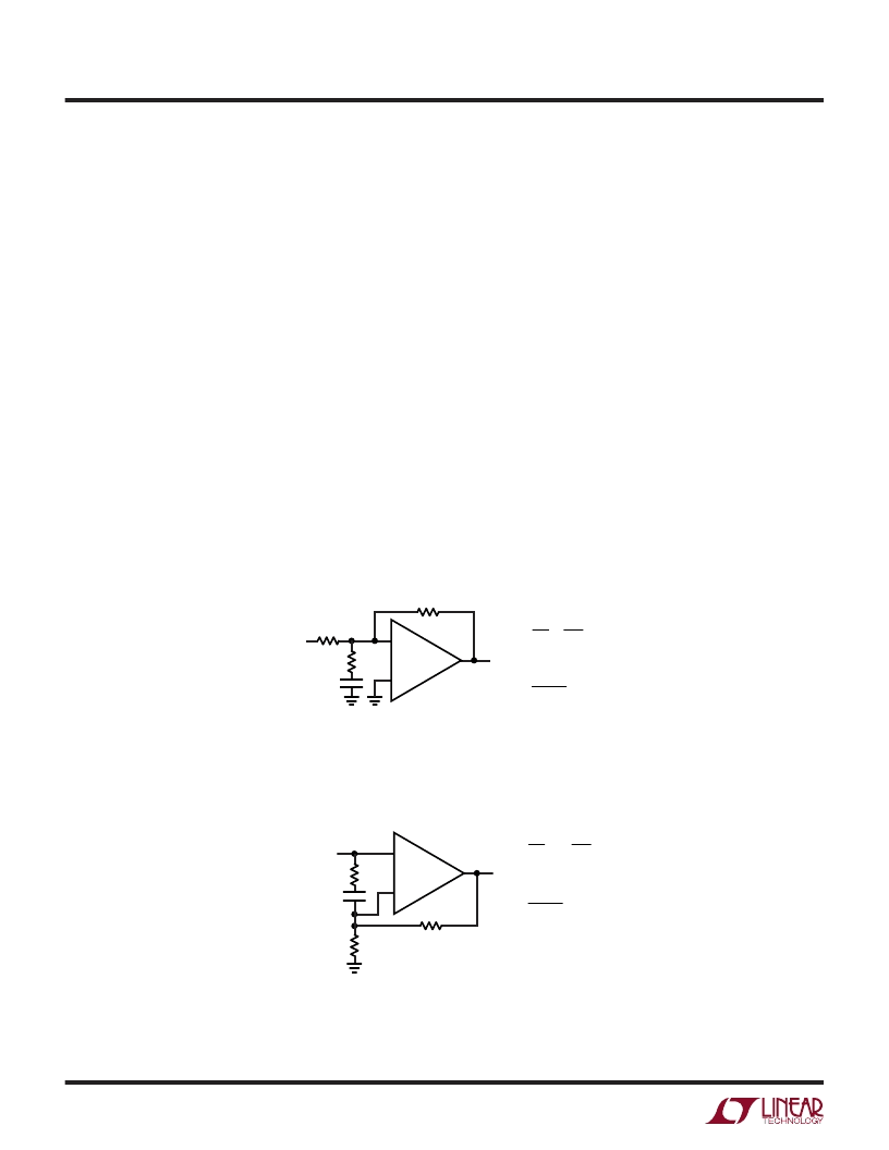
Figure 2. Compensation for Inverting Gains
R
G
R
C
V
o
V
i
C
C
(OPTIONAL)
–
+
1969 F02
R
F
= –R
F
R
G
V
o
V
i
< 15MHz
1
2
π
R
C
C
C
(R
C
|| R
G
)
≤
R
F
/9
Figure 3. Compensation for Noninverting Gains
R
C
V
o
V
i
C
C
(OPTIONAL)
+
–
1969 F03
R
F
R
G
= 1 +
R
F
R
G
V
o
V
i
< 15MHz
1
2
π
R
C
C
C
(R
C
|| R
G
)
≤
R
F
/9
Compensation
The LT1969 is stable in a gain 10 or higher for any supply
and resistive load. It is easily compensated for lower gains
with a single resistor or a resistor plus a capacitor.
Figure2 shows that for inverting gains, a resistor from the
inverting node to AC ground guarantees stability if the
parallel combination of R
C
and R
G
is less than or equal to
R
F
/9. For lowest distortion and DC output offset, a series
capacitor, C
C
, can be used to reduce the noise gain at lower
frequencies. The break frequency produced by R
C
and C
C
should be less than 15MHz to minimize peaking. The
Typical Curve of Frequency Response vs Supply Voltage,
A
V
= –1 shows less than 1dB of peaking for a break
frequency of 12.8MHz.
Figure 3 shows compensation in the noninverting configu-
ration. The R
C
, C
C
network acts similarly to the inverting
case. The input impedance is not reduced because the
相關(guān)PDF資料 |
PDF描述 |
|---|---|
| LTJ811G | Optoelectronic |
| LTJ811HR | Optoelectronic |
| LTJ811Y | Optoelectronic |
| LTK4N25 | Optoelectronic |
| LTK4N25V | Optoelectronic |
相關(guān)代理商/技術(shù)參數(shù) |
參數(shù)描述 |
|---|---|
| LTIGAB51-6S-BL-RC-MBL-XSW1 | 制造商:Carling Technologies 功能描述:LTIG, H, & L-SERIES RKR SW - Bulk |
| LTIGAB51-6S-WH-AM-NBL-XHA1 | 制造商:Carling Technologies 功能描述:LTIG, H, & L-SERIES RKR SW - Bulk |
| LTIGAB51-6S-WH-RC-WBLXTR5 | 制造商:Carling Technologies 功能描述:LTIG, H, & L-SERIES RKR SW - Bulk |
| LTIGAB53-6S-BL-RC-XWA1 | 制造商:Carling Technologies 功能描述:LTIG, H, & L-SERIES RKR SW - Bulk |
| LTIGAB56-7S-WH-RC-AXAC4 | 制造商:Carling Technologies 功能描述:LTIG, H, & L-SERIES RKR SW - Bulk |
發(fā)布緊急采購(gòu),3分鐘左右您將得到回復(fù)。