- 您現(xiàn)在的位置:買賣IC網(wǎng) > PDF目錄44987 > LT4180MPGN#TRPBF (LINEAR TECHNOLOGY CORP) POWER SUPPLY SUPPORT CKT, PDSO24 PDF資料下載
參數(shù)資料
| 型號(hào): | LT4180MPGN#TRPBF |
| 廠商: | LINEAR TECHNOLOGY CORP |
| 元件分類: | 電源管理 |
| 英文描述: | POWER SUPPLY SUPPORT CKT, PDSO24 |
| 封裝: | 0.150 INCH, LEAD FREE, PLASTIC, SSOP-24 |
| 文件頁(yè)數(shù): | 14/18頁(yè) |
| 文件大?。?/td> | 278K |
| 代理商: | LT4180MPGN#TRPBF |
第1頁(yè)第2頁(yè)第3頁(yè)第4頁(yè)第5頁(yè)第6頁(yè)第7頁(yè)第8頁(yè)第9頁(yè)第10頁(yè)第11頁(yè)第12頁(yè)第13頁(yè)當(dāng)前第14頁(yè)第15頁(yè)第16頁(yè)第17頁(yè)第18頁(yè)

LT4180
5
4180fa
PIN FUNCTIONS
INTVCC (Pin 1): The LDO Output. A low ESR ceramic
capacitor provides decoupling and output compensation.
1μF or more should be used.
DRAIN (Pin 2): Open-Drain of the Output Transistor. This
pin drives either the LED in an opto-isolator, or pulls down
on the regulator control pin.
COMP (Pin 3): Gate of the Output Transistor. This pin allows
additional compensation. It must be left open if unused.
CHOLD1 (Pin 4): Connects to track/hold amplier hold
capacitor. The other end of this capacitor should be Kelvin
connected to GND.
GUARD2 (Pin 5): Guard Ring Drive for CHOLD2.
CHOLD2 (Pin 6): Connects to track/hold amplier hold
capacitor. The other end of this capacitor should be Kelvin
connected to GND.
GUARD3 (Pin 7): Guard Ring Drive for CHOLD3.
CHOLD3 (Pin 8): Connects to track/hold amplier hold
capacitor. The other end of this capacitor should be Kelvin
connected to GND.
GUARD4 (Pin 9): Guard Ring Drive for CHOLD4.
CHOLD4 (Pin 10): Connects to track/hold amplier hold
capacitor. The other end of this capacitor should be Kelvin
connected to GND.
FB (Pin 11): Receives the feedback voltage from an exter-
nal resistor divider across the main output. An (optional)
capacitor to ground may be added to eliminate high
frequency noise. The time constant for this RC network
should be no greater than 0.1 times the dither frequency.
For example, with fDITHER = 1kHz, τ = 0.1ms.
GND (Pin 12): Ground.
COSC (Pin 13): Oscillator Timing Capacitor. Oscillator fre-
quency is set by this capacitor and ROSC. For best accuracy,
the minimum recommended capacitance is 100pF.
ROSC (Pin 14): Oscillator Timing Resistor. Oscillator
frequency is set by this resistor and COSC.
OSC (Pin 15): Oscillator Output. This output may be
used to synchronize the switching regulator to the
Virtual Remote Sense. This is a high current output capable
of driving opto-isolators. Other isolation methods may
also be used with this output.
DIV2 (Pin 16): Dither Division Ratio Programming Pin.
DIV1 (Pin 17): Dither Division Ratio Programming Pin.
DIV0 (Pin 18): Dither Division Ratio Programming Pin.
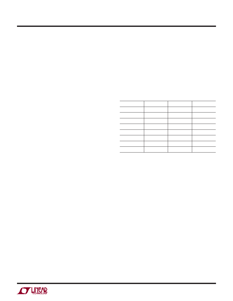
Use the following table to program the dither division
ratio (fOSC/fDITHER)
Table 1. Programming the Dither Division Ratio (fOSC/fDITHER)
DIV2
DIV1
DIV0
DIVISION RATIO
0008
001
16
010
32
011
64
100
128
101
256
110
512
1
1024
For example, fDITHER = fOSC /128 with DIV2 = 1 and DIV1
= DIV0 = 0.
SPREAD (Pin 19): Spread Spectrum Enable Input. Dither
phasing is pseudo-randomly adjusted when SPREAD is
tied high.
OV (Pin 20): Overvoltage Comparator Input. This prevents
line drop correction when wiring drops would cause ex-
cessive switching power supply output voltage. Set OV
so VREG(MAX) ≤ 1.50VLOAD.
RUN (Pin 21): The RUN pin provides the user with an accu-
rate means for sensing the input voltage and programming
the start-up threshold for the line drop corrector.
SENSE (Pin 22): Current Sense Input. This input connects
to the current sense resistor. Kelvin connect to RSENSE.
VPP (Pin 23): Connect this pin to INTVCC.
VIN(Pin24):MainSupplyPin.VINmustbelocallybypassed
to ground. Kelvin connect the current sense resistor to
this pin and minimize interconnect resistance.
相關(guān)PDF資料 |
PDF描述 |
|---|---|
| LT4250HCN8#TRPBF | 1-CHANNEL POWER SUPPLY SUPPORT CKT, PDIP8 |
| LT4356CS-3 | SPECIALTY ANALOG CIRCUIT, PDSO16 |
| LT4356IMS-3 | SPECIALTY ANALOG CIRCUIT, PDSO10 |
| LT4356HMS-3#PBF | SPECIALTY ANALOG CIRCUIT, PDSO10 |
| LT4356IS-3 | SPECIALTY ANALOG CIRCUIT, PDSO16 |
相關(guān)代理商/技術(shù)參數(shù) |
參數(shù)描述 |
|---|---|
| LT41EC | 制造商:LAUREL ELECTRONICS 功能描述:LT Series transmitter with dual solid state relays, isolated 4-20 mA and RS232/R |
| LT41EF | 制造商:LAUREL ELECTRONICS 功能描述:LT Series transmitter with dual solid state relays, isolated 4-20 mA and RS232/R |
| LT41JF | 制造商:LAUREL ELECTRONICS 功能描述:LT Series transmitter with dual solid state relays, isolated 4-20 mA and RS232/R |
| LT41KC | 制造商:LAUREL ELECTRONICS 功能描述:LT Series transmitter with dual solid state relays, isolated 4-20 mA and RS232/R |
| LT41KF | 制造商:LAUREL ELECTRONICS 功能描述:LT Series transmitter with dual solid state relays, isolated 4-20 mA and RS232/R |
發(fā)布緊急采購(gòu),3分鐘左右您將得到回復(fù)。