- 您現(xiàn)在的位置:買賣IC網(wǎng) > PDF目錄358934 > LPC47M112-MC (STANDARD MICROSYSTEMS CORP) ENHANCED SUPER I/O CONTROLLER WITH LPC INTERFACE PDF資料下載
參數(shù)資料
| 型號: | LPC47M112-MC |
| 廠商: | STANDARD MICROSYSTEMS CORP |
| 元件分類: | 外設及接口 |
| 英文描述: | ENHANCED SUPER I/O CONTROLLER WITH LPC INTERFACE |
| 中文描述: | MULTIFUNCTION PERIPHERAL, PQFP100 |
| 封裝: | 14 X 20 MM, QFP-100 |
| 文件頁數(shù): | 220/228頁 |
| 文件大小: | 1269K |
| 代理商: | LPC47M112-MC |
第1頁第2頁第3頁第4頁第5頁第6頁第7頁第8頁第9頁第10頁第11頁第12頁第13頁第14頁第15頁第16頁第17頁第18頁第19頁第20頁第21頁第22頁第23頁第24頁第25頁第26頁第27頁第28頁第29頁第30頁第31頁第32頁第33頁第34頁第35頁第36頁第37頁第38頁第39頁第40頁第41頁第42頁第43頁第44頁第45頁第46頁第47頁第48頁第49頁第50頁第51頁第52頁第53頁第54頁第55頁第56頁第57頁第58頁第59頁第60頁第61頁第62頁第63頁第64頁第65頁第66頁第67頁第68頁第69頁第70頁第71頁第72頁第73頁第74頁第75頁第76頁第77頁第78頁第79頁第80頁第81頁第82頁第83頁第84頁第85頁第86頁第87頁第88頁第89頁第90頁第91頁第92頁第93頁第94頁第95頁第96頁第97頁第98頁第99頁第100頁第101頁第102頁第103頁第104頁第105頁第106頁第107頁第108頁第109頁第110頁第111頁第112頁第113頁第114頁第115頁第116頁第117頁第118頁第119頁第120頁第121頁第122頁第123頁第124頁第125頁第126頁第127頁第128頁第129頁第130頁第131頁第132頁第133頁第134頁第135頁第136頁第137頁第138頁第139頁第140頁第141頁第142頁第143頁第144頁第145頁第146頁第147頁第148頁第149頁第150頁第151頁第152頁第153頁第154頁第155頁第156頁第157頁第158頁第159頁第160頁第161頁第162頁第163頁第164頁第165頁第166頁第167頁第168頁第169頁第170頁第171頁第172頁第173頁第174頁第175頁第176頁第177頁第178頁第179頁第180頁第181頁第182頁第183頁第184頁第185頁第186頁第187頁第188頁第189頁第190頁第191頁第192頁第193頁第194頁第195頁第196頁第197頁第198頁第199頁第200頁第201頁第202頁第203頁第204頁第205頁第206頁第207頁第208頁第209頁第210頁第211頁第212頁第213頁第214頁第215頁第216頁第217頁第218頁第219頁當前第220頁第221頁第222頁第223頁第224頁第225頁第226頁第227頁第228頁
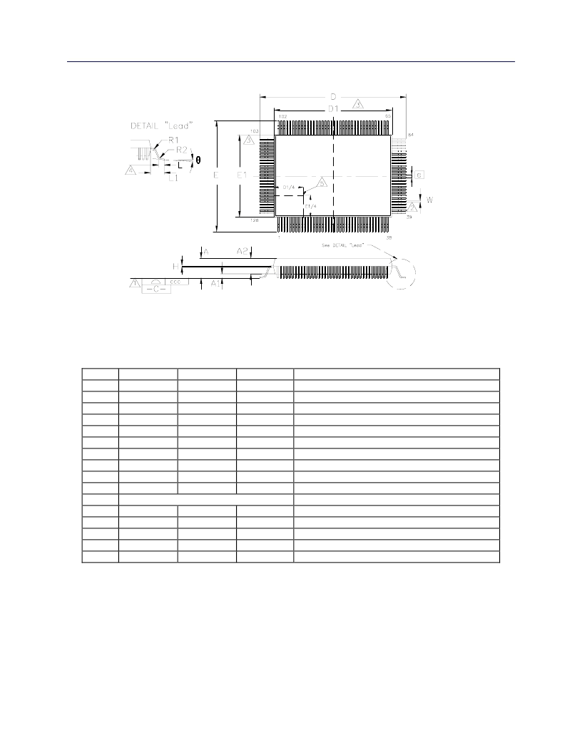
13 PACKAGE OUTLINE
SMSC DS – LPC47M192
Page 220
Rev. 03/30/05
DATASHEET
FIGURE 45 – 128 PIN QFP PACKAGE OUTLINE, 14x20x2.7 BODY, 3.2 MM FOOTPRINT
MIN
~
0.05
2.55
23.00
19.90
17.00
13.90
0.09
0.73
~
NOMINAL
~
~
~
23.20
20.00
17.20
14.00
~
0.88
1.60
0.50 Basic
~
~
~
~
~
MAX
3.4
0.5
3.05
23.40
20.10
17.40
14.10
0.20
1.03
~
REMARKS
A
A1
A2
D
D1
E
E1
H
L
L1
e
θ
W
R1
R2
ccc
Overall Package Height
Standoff
Body Thickness
X Span
X body Size
Y Span
Y body Size
Lead Frame Thickness
Lead Foot Length
Lead Length
Lead Pitch
Lead Foot Angle
Lead Width
Lead Shoulder Radius
Lead Foot Radius
Coplanarity
0
o
0.10
0.08
0.08
~
7
o
0.30
~
0.30
0.08
Notes:
1
Controlling Unit: millimeter.
2
Tolerance on the position of the leads is ± 0.04 mm maximum.
3
Package body dimensions D1 and E1 do not include the mold protrusion.
Maximum mold protrusion is 0.25 mm.
4
Dimension for foot length L measured at the gauge plane 0.25 mm above the seating plane.
5
Details of pin 1 identifier are optional but must be located within the zone indicated.
相關PDF資料 |
PDF描述 |
|---|---|
| LPC47M112-MW | ENHANCED SUPER I/O CONTROLLER WITH LPC INTERFACE |
| LPC47N252-SD | Advanced Notebook I/O Controller with On-Board FLASH |
| LPC47N252-SG | Advanced Notebook I/O Controller with On-Board FLASH |
| LPC47M172-NR | ADVANCED I/O CONTROLLER WITH MOTHERBOARD GLUE LOGIC |
| LPC47N267-MN | 100 Pin LPC Notebook I/O with X-Bus Interface |
相關代理商/技術(shù)參數(shù) |
參數(shù)描述 |
|---|---|
| LPC47M112-MW | 功能描述:以太網(wǎng) IC Enhanced Super I/O Cntrl LPC Interface RoHS:否 制造商:Micrel 產(chǎn)品:Ethernet Switches 收發(fā)器數(shù)量:2 數(shù)據(jù)速率:10 Mb/s, 100 Mb/s 電源電壓-最大:1.25 V, 3.45 V 電源電壓-最小:1.15 V, 3.15 V 最大工作溫度:+ 85 C 封裝 / 箱體:QFN-64 封裝:Tray |
| LPC47M133-NC | 制造商:SMSC 功能描述: |
| LPC47M140-NC | 制造商:SMSC 制造商全稱:SMSC 功能描述:128 PIN ENGANCED SUPER I/O CONTROLLER WITH AN LPC INTERFACE AND USB HUB |
| LPC47M141-NC | 制造商:SMSC 制造商全稱:SMSC 功能描述:128 PIN ENGANCED SUPER I/O CONTROLLER WITH AN LPC INTERFACE AND USB HUB |
| LPC47M142-NC | 制造商:Rochester Electronics LLC 功能描述:- Bulk |
發(fā)布緊急采購,3分鐘左右您將得到回復。