- 您現(xiàn)在的位置:買賣IC網(wǎng) > PDF目錄385488 > LM6211MFX (NATIONAL SEMICONDUCTOR CORP) Low Noise, RRO Operational Amplifier with CMOS Input and 24V Operation PDF資料下載
參數(shù)資料
| 型號: | LM6211MFX |
| 廠商: | NATIONAL SEMICONDUCTOR CORP |
| 元件分類: | 運(yùn)動(dòng)控制電子 |
| 英文描述: | Low Noise, RRO Operational Amplifier with CMOS Input and 24V Operation |
| 中文描述: | OP-AMP, 2800 uV OFFSET-MAX, 17 MHz BAND WIDTH, PDSO5 |
| 封裝: | SOT-23, 5 PIN |
| 文件頁數(shù): | 16/19頁 |
| 文件大?。?/td> | 1091K |
| 代理商: | LM6211MFX |
Typical Applications
(Continued)
AUDIO PREAMPLIFIER
With low input referred voltage noise, low supply voltage and
low supply current, and low harmonic distortion, the LM6211
is ideal for audio applications. Its wide unity gain bandwidth
allows it to provide large gain over a wide frequency range
and it can be used to design a preamplifier to drive a load of
as low as 600
with less than 0.001% distortion. Two am-
plifier circuits are shown in
Figure 10
and
Figure 11
.
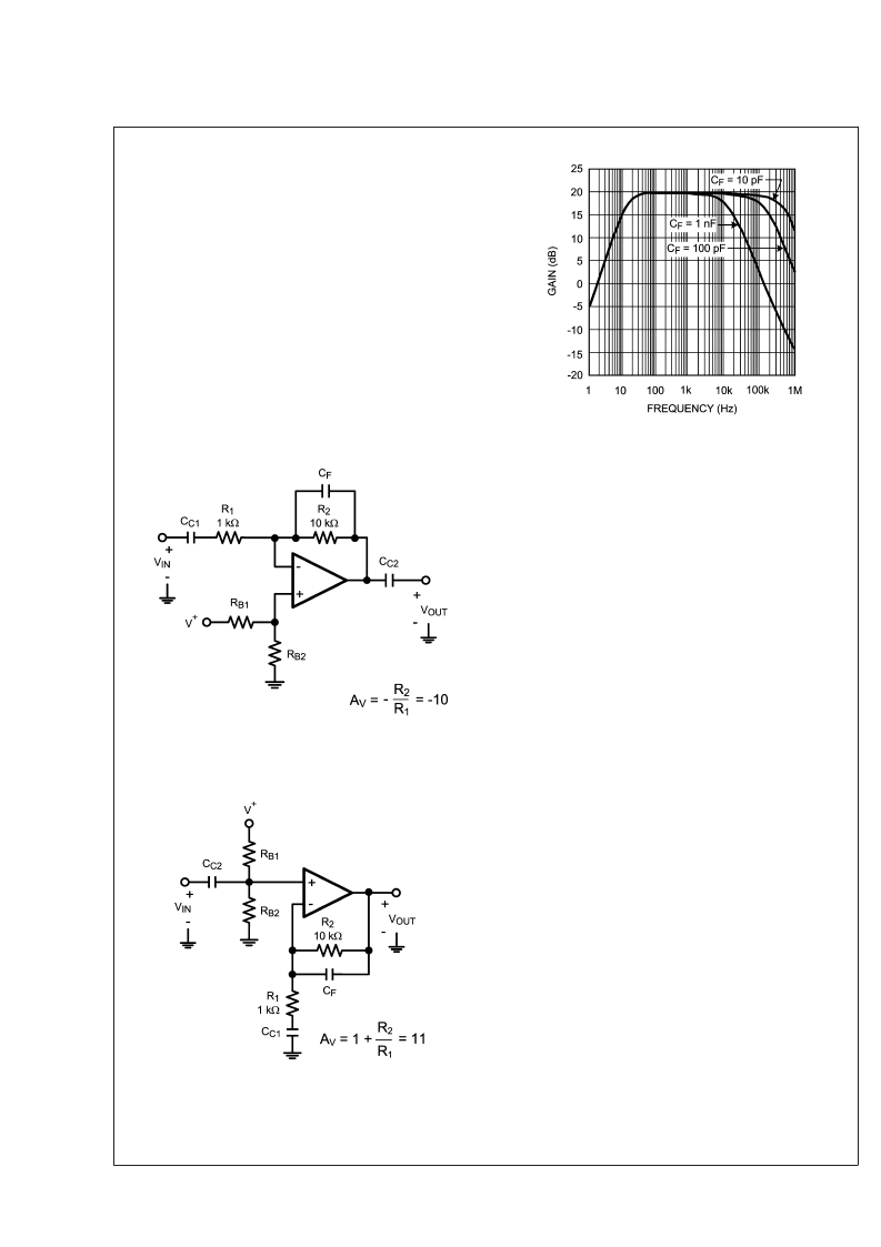
Figure
10
is an inverting amplifier, with a 10 k
feedback resistor,
R
2
, and a 1 k
input resistor, R
1
, and hence provides a gain
of 10.
Figure 11
is a non-inverting amplifier, using the same
values for R
1
and R
2
, and provides a gain of 11. In either of
these circuits, the coupling capacitor C
C1
decides the lower
frequency at which the circuit starts providing gain, while the
feedback capacitor C
decides the frequency at which the
gain starts dropping off.
Figure 12
shows the frequency
response of the circuit in
Figure 10
with different values of
C
F
.
TRANSIMPEDANCE AMPLIFIER
A transimpedance amplifier converts a small input current
into a voltage. This current is usually generated by a photo-
diode. The transimpedance gain, measured as the ratio of
the output voltage to the input current, is expected to be
large and wide-band. Since the circuit deals with currents in
the range of a few nA, low noise performance is essential.
The LM6211, being a CMOS input op amp, provides a wide
bandwidth and low noise performance while drawing very
low input bias current, and is hence ideal for transimpedance
applications.
A transimpedance amplifier is designed on the basis of the
current source driving the input. A photodiode is a very
common capacitive current source, which requires transim-
pedance gain for transforming its miniscule current into eas-
ily detectable voltages. The photodiode and amplifier’s gain
are selected with respect to the speed and accuracy re-
quired of the circuit. A faster circuit would require a photo-
diode with lesser capacitance and a faster amplifier. A more
sensitive circuit would require a sensitive photodiode and a
high gain. A typical transimpedance amplifier is shown in
Figure 13
. The output voltage of the amplifier is given by the
equation V
= I
R
. Since the output swing of the am-
plifier is limited, R
should be selected such that all possible
values of I
IN
can be detected.
The LM6211 has a large gain-bandwidth product (20 MHz),
which enables high gains at wide bandwidths. A rail-to-rail
output swing at 24V supply allows detection and amplifica-
tion of a wide range of input currents. A CMOS input stage
with negligible input current noise and low input voltage
noise allows the LM6211 to provide high fidelity amplification
for wide bandwidths. These properties make the LM6211
ideal for systems requiring wide-band transimpedance am-
plification.
20120341
FIGURE 10. Inverting Audio Amplifier
20120342
FIGURE 11. Non-Inverting Audio Preamplifier
20120343
FIGURE 12. Frequency Response of the Non-Inverting
Preamplifier
L
www.national.com
16
相關(guān)PDF資料 |
PDF描述 |
|---|---|
| LM62CIM3X | 2.7V, 15.6 mV/∑C SOT-23 Temperature Sensor |
| LM62BIM3 | 2.7V, 15.6 mV/∑C SOT-23 Temperature Sensor |
| LM62BIM3X | 2.7V, 15.6 mV/∑C SOT-23 Temperature Sensor |
| LM62CIM3 | 2.7V, 15.6 mV/∑C SOT-23 Temperature Sensor |
| LM6310 | High Speed Low Power Operational Amplifier with TRI-STATE Output |
相關(guān)代理商/技術(shù)參數(shù) |
參數(shù)描述 |
|---|---|
| LM6211MFX/NOPB | 功能描述:運(yùn)算放大器 - 運(yùn)放 RoHS:否 制造商:STMicroelectronics 通道數(shù)量:4 共模抑制比(最小值):63 dB 輸入補(bǔ)償電壓:1 mV 輸入偏流(最大值):10 pA 工作電源電壓:2.7 V to 5.5 V 安裝風(fēng)格:SMD/SMT 封裝 / 箱體:QFN-16 轉(zhuǎn)換速度:0.89 V/us 關(guān)閉:No 輸出電流:55 mA 最大工作溫度:+ 125 C 封裝:Reel |
| LM6218 | 制造商:未知廠家 制造商全稱:未知廠家 功能描述: |
| LM6218AH | 制造商:未知廠家 制造商全稱:未知廠家 功能描述:Voltage-Feedback Operational Amplifier |
| LM6218AJ | 制造商:未知廠家 制造商全稱:未知廠家 功能描述:Voltage-Feedback Operational Amplifier |
| LM6218AN | 制造商:NSC 制造商全稱:National Semiconductor 功能描述:Fast Settling Dual Operational Amplifiers |
發(fā)布緊急采購,3分鐘左右您將得到回復(fù)。