- 您現(xiàn)在的位置:買賣IC網(wǎng) > PDF目錄385488 > LM5041 (National Semiconductor Corporation) Cascaded PWM Controller PDF資料下載
參數(shù)資料
| 型號: | LM5041 |
| 廠商: | National Semiconductor Corporation |
| 英文描述: | Cascaded PWM Controller |
| 中文描述: | 級聯(lián)PWM控制器 |
| 文件頁數(shù): | 11/16頁 |
| 文件大小: | 343K |
| 代理商: | LM5041 |
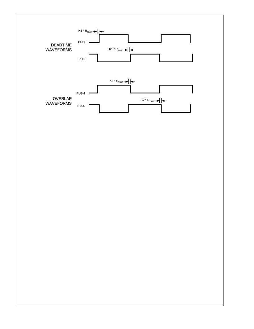
Push-Pull Outputs
(Continued)
20074904
PWM Comparator
The PWM comparator compares the slope compensated
current ramp signal to the loop error voltage from the internal
error amplifier (COMP pin). This comparator is optimized for
speed in order to achieve minimum controllable duty cycles.
The comparator polarity is such that 0V on the COMP pin will
produce zero duty cycle in the buck stage.
Error Amplifier
An internal high gain wide-bandwidth error amplifier is pro-
vided within the LM5041. The amplifier’s non-inverting input
is tied to a 0.75V reference. The inverting input is connected
to the FB pin. In non-isolated applications the power con-
verter output is connected to the FB pin via the voltage
setting resistors. Loop compensation components are con-
nected between the COMP and FB pins. For most isolated
applications the error amplifier function is implemented on
the secondary side of the converter and the internal error
amp is not used. The internal error amplifier is configured as
an open drain output and can be disabled by connecting the
FB pin to ground. An internal 5k
pull-up resistor between
the 5V reference and COMP can be used as the pull-up for
an opto-coupler in isolated applications.
Current Limit/Current Sense
The LM5041 contains two levels of over-current protection. If
the voltage at the CS pin exceeds 0.5V the present buck
stage duty cycle is terminated (cycle by cycle current limit). If
the voltage at the CS pin overshoots the 0.5V threshold and
exceeds 0.6V, then the controller will terminate the present
cycle and fully discharge the soft-start capacitor. A small RC
filter located near the controller is recommended to filter
current sense signals at the CS pin. An internal MOSFET
discharges the external CS pin for an additional 50ns at the
beginning of each cycle to reduce the leading edge spike
that occurs when the buck stage MOSFET is turned on.
The LM5041 current sense and PWM comparators are very
fast, and may respond to short duration noise pulses. Layout
considerations are critical for the current sense filter and
sense resistor. The capacitor associated with the CS filter
must be placed close to the device and connected directly to
the pins of the controller (CS and GND). If a current sense
transformer is used, both leads of the transformer secondary
should be routed to the sense resistor, which should also be
located close to the IC. A resistor may be used for current
sensing instead of a transformer, located in the push-pull
transistor sources, but a low inductance type of resistor is
required. When designing with a sense resistor, all of the
noise sensitive low power grounds should be connected
together around the IC and a single connection should be
made to the high current power ground (sense resistor
ground point).
The second level current sense threshold is intended to
protect the power converter by initiating a low duty cycle
hick-up mode when abnormally high currents are sensed. If
the second level threshold is reached, the soft-start capaci-
tor will be discharged and a start-up sequence will com-
mence when the soft-start capacitor is determined to be fully
discharged. The second level threshold will only be reached
when a high dV/dt is present at the current sense pin. The
current sense transient must be fast enough to reach the
second level threshold before the first threshold detector
turns off the buck stage driver. Very high current sense dV/dt
can occur with a saturated power inductor or shorted load.
Excessive filtering on the CS pin such as an extremely low
value current sense resistor or an inductor that does not
saturate with excessive loading, may prevent the second
level threshold from being reached. If the second level
threshold is never exceeded during an overload condition,
the first level current sense will continue cycle by cycle
limiting and the output characteristic of the converter will be
that of a current source. However, a sustained overload
current level can cause excessive temperatures in the power
train especially the output rectifiers.
Oscillator and Sync Capability
The LM5041 oscillator is set by a single external resistor
connected between the RT pin and GND. To set a desired
oscillator frequency (F), the necessary RT resistor can be
calculated from:
L
www.national.com
11
相關(guān)PDF資料 |
PDF描述 |
|---|---|
| LM5041MTC | Cascaded PWM Controller |
| LM5041MTCX | Cascaded PWM Controller |
| LM5041SD | Cascaded PWM Controller |
| LM5041SDX | Cascaded PWM Controller |
| LM5104 | High Voltage Half-Bridge Gate Driver with Adaptive Delay |
相關(guān)代理商/技術(shù)參數(shù) |
參數(shù)描述 |
|---|---|
| LM5041A | 制造商:NSC 制造商全稱:National Semiconductor 功能描述:Cascaded PWM Controller |
| LM5041AMTC | 功能描述:電流型 PWM 控制器 RoHS:否 制造商:Texas Instruments 開關(guān)頻率:27 KHz 上升時間: 下降時間: 工作電源電壓:6 V to 15 V 工作電源電流:1.5 mA 輸出端數(shù)量:1 最大工作溫度:+ 105 C 安裝風(fēng)格:SMD/SMT 封裝 / 箱體:TSSOP-14 |
| LM5041AMTC/NOPB | 功能描述:電流型 PWM 控制器 RoHS:否 制造商:Texas Instruments 開關(guān)頻率:27 KHz 上升時間: 下降時間: 工作電源電壓:6 V to 15 V 工作電源電流:1.5 mA 輸出端數(shù)量:1 最大工作溫度:+ 105 C 安裝風(fēng)格:SMD/SMT 封裝 / 箱體:TSSOP-14 |
| LM5041AMTC-NOPB | 制造商:TI 制造商全稱:Texas Instruments 功能描述:LM5041A Cascaded PWM Controller |
| LM5041AMTCX | 功能描述:電流型 PWM 控制器 RoHS:否 制造商:Texas Instruments 開關(guān)頻率:27 KHz 上升時間: 下降時間: 工作電源電壓:6 V to 15 V 工作電源電流:1.5 mA 輸出端數(shù)量:1 最大工作溫度:+ 105 C 安裝風(fēng)格:SMD/SMT 封裝 / 箱體:TSSOP-14 |
發(fā)布緊急采購,3分鐘左右您將得到回復(fù)。