- 您現(xiàn)在的位置:買賣IC網(wǎng) > PDF目錄385480 > LM3202TLX (NATIONAL SEMICONDUCTOR CORP) 650mA Miniature, Adjustable, Step-Down DC-DC Converter for RF Power Amplifiers PDF資料下載
參數(shù)資料
| 型號: | LM3202TLX |
| 廠商: | NATIONAL SEMICONDUCTOR CORP |
| 元件分類: | 穩(wěn)壓器 |
| 英文描述: | 650mA Miniature, Adjustable, Step-Down DC-DC Converter for RF Power Amplifiers |
| 中文描述: | 1.2 A SWITCHING REGULATOR, 2300 kHz SWITCHING FREQ-MAX, BGA8 |
| 封裝: | LEAD FREE, MICRO SMD , 8 PIN |
| 文件頁數(shù): | 13/15頁 |
| 文件大小: | 1507K |
| 代理商: | LM3202TLX |
Application Information
(Continued)
CAPACITOR SELECTION
The LM3202 is designed for ceramic capacitor for its input
and output filters. Use a 10μF ceramic capacitor for input
and a 4.7μF ceramic capacitor for output. Ceramic capaci-
tors types such as X5R, X7R are recommended to use for
both filters. These provide an optimal balance between small
size, cost, reliability and performance for cell phones and
similar applications.
Table 3
lists suggests some part num-
bers and suppliers. DC bias characteristics of the capacitors
must be considered when selecting the voltage rating and
case size of the capacitor. Smaller case sizes for the output
mitigates piezo electric vibrations of the capacitor when the
output voltage is stepped up and down at fast rates however
they have a bigger percentage drop in value with dc bias.
Use of multiple 2.2μF or 1μF capacitors can also be consid-
ered.
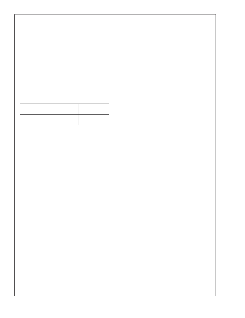
TABLE 3. Suggested capacitors and their suppliers
Model
Vendor
Taiyo-Yuden
MuRata
TDK
JMK212BJ475, 4.7μF, 6.3V
GRM188R60J475, 4.7μF, 6.3V
C2012X5R0J106,10μF, 6.3V
The input filter capacitor supplies AC current drawn by the
PFET switch of the LM3202 in the first part of each cycle and
reduces the voltage ripple imposed on the input power
source. The output filter capacitor absorbs the AC inductor
current, helps maintain a steady output voltage during tran-
sient load changes and reduces output voltage ripple. These
capacitors must be selected with sufficient capacitance and
sufficiently low ESR (Equivalent Series Resistance) to per-
form these functions. The ESR of the filter capacitors is
generally a major factor in voltage ripple.
EN PIN CONTROL
Drive the EN pin using the system controller to turn the
LM3202 ON and OFF. Use a comparator, Schmidt trigger or
logic gate to drive the EN pin. Set EN high (
>
1.2V) for
normal operation and low (
<
0.5V) for a 0.01μA (typ.) shut-
down mode.
Set EN low to turn off the LM3202 during power-up and
under voltage conditions when the power supply is less than
the 2.7V minimum operating voltage. The part is out of
regulation when the input voltage is less than 2.7V. The
LM3202 is designed for mobile phones where the system
controller controls operation mode for maximizing battery life
and requirements for small package size outweigh the addi-
tional size required for inclusion of UVLO (Under Voltage
Lock-Out) circuitry.
Micro SMD PACKAGE ASSEMBLY AND USE
Use of the Micro SMD package requires specialized board
layout, precision mounting and careful re-flow techniques, as
detailed in National Semiconductor Application Note 1112.
Refer to the section
Surface Mount Technology (SMD) As-
sembly Considerations.
For best results in assembly, align-
ment ordinals on the PC board should be used to facilitate
placement of the device. The pad style used with Micro SMD
package must be the NSMD (non-solder mask defined) type.
This means that the solder-mask opening is larger than the
pad size. This prevents a lip that otherwise forms if the
solder-mask and pad overlap, from holding the device off the
surface of the board and interfering with mounting. See
Application Note 1112 for specific instructions how to do this.
The 8-Bump package used for LM3202 has 300micron sol-
der balls and requires 10.82mil pads for mounting on the
circuit board. The trace to each pad should enter the pad
with a 90entry angle to prevent debris from being caught in
deep corners. Initially, the trace to each pad should be 7mil
wide, for a section approximately 7mil long , as a thermal
relief. Then each trace should neck up or down to its optimal
width. The important criterion is symmetry. This ensures the
solder bumps on the LM3202 re-flow evenly and that the
device solders level to the board. In particular, special atten-
tion must be paid to the pads for bumps A1, A3 and B3.
Because PGND and PVIN are typically connected to large
copper planes, inadequate thermal relief’s can result in late
or inadequate re-flow of these bumps.
The Micro SMD package is optimized for the smallest pos-
sible size in applications with red or infrared opaque cases.
Because the Micro SMD package lacks the plastic encapsu-
lation characteristic of larger devices, it is vulnerable to light.
Backside metallization and/or epoxy coating, along with
front-side shading by the printed circuit board, reduce this
sensitivity. However, the package has exposed die edges. In
particular, Micro SMD devices are sensitive to light, in the
red and infrared range, shining on the package’s exposed
die edges.
BOARD LAYOUT CONSIDERATIONS
PC board layout is an important part of DC-DC converter
design. Poor board layout can disrupt the performance of a
DC-DC converter and surrounding circuitry by contributing to
EMI, ground bounce, and resistive voltage loss in the traces.
These can send erroneous signals to the DC-DC converter
IC, resulting in poor regulation or instability. Poor layout can
also result in re-flow problems leading to poor solder joints
between the Micro SMD package and board pads. Poor
solder joints can result in erratic or degraded performance.
Good layout for the LM3202 can be implemented by follow-
ing a few simple design rules.
1.
Place the LM3202 on 10.82mil pads. As a thermal relief,
connect to each pad with a 7mil wide, approximately
7mil long traces, and when incrementally increase each
trace to its optimal width. The important criterion is sym-
metry to ensure the solder bumps on the LM3202 re-flow
evenly (
see Micro SMD Package Assembly and Use
).
2.
Place the LM3202, inductor and filter capacitors close
together and make the trace short. The traces between
these components carry relatively high switching cur-
rents and act as antennas. Following this rule reduces
radiated noise. Place the capacitors and inductor within
0.2inch (5mm) of the LM3202.
3.
Arrange the components so that the switching current
loops curl in the same direction. During the first half of
each cycle, current flows from the input filter capacitor,
through the LM3202 and inductor to the output filter
capacitor and back through ground, forming a current
loop. In the second half of each cycle, current is pulled
up from ground, through the LM3202 by the inductor, to
the output filter capacitor and then back through ground,
forming a second current loop. Routing these loops so
the current curls in the same direction prevents mag-
netic field reversal between the two half-cycles and re-
duces radiated noise.
L
www.national.com
13
相關PDF資料 |
PDF描述 |
|---|---|
| LM3207 | 650mA Miniature, Adjustable, Step-Down DC-DC Converter for RF Power Amplifiers with Integrated Vref LDO |
| LM3207TL | 650mA Miniature, Adjustable, Step-Down DC-DC Converter for RF Power Amplifiers with Integrated Vref LDO |
| LM3207TLX | 650mA Miniature, Adjustable, Step-Down DC-DC Converter for RF Power Amplifiers with Integrated Vref LDO |
| LM3208 | 650mA Miniature, Adjustable, Step-Down DC-DC Converter for RF Power Amplifiers |
| LM3208TL | 650mA Miniature, Adjustable, Step-Down DC-DC Converter for RF Power Amplifiers |
相關代理商/技術參數(shù) |
參數(shù)描述 |
|---|---|
| LM3202TLX/NOPB | 功能描述:DC/DC 開關控制器 RoHS:否 制造商:Texas Instruments 輸入電壓:6 V to 100 V 開關頻率: 輸出電壓:1.215 V to 80 V 輸出電流:3.5 A 輸出端數(shù)量:1 最大工作溫度:+ 125 C 安裝風格: 封裝 / 箱體:CPAK |
| LM3203 | 制造商:NSC 制造商全稱:National Semiconductor 功能描述:Step-Down DC-DC Converter with Bypass Mode for CDMA / WCDMA RF Power Amplifiers |
| LM3203TL | 制造商:Texas Instruments 功能描述:CONVERTER BUCK 0.5A ADJ POWERWISE |
| LM3203TL/NOPB | 功能描述:DC/DC 開關控制器 RoHS:否 制造商:Texas Instruments 輸入電壓:6 V to 100 V 開關頻率: 輸出電壓:1.215 V to 80 V 輸出電流:3.5 A 輸出端數(shù)量:1 最大工作溫度:+ 125 C 安裝風格: 封裝 / 箱體:CPAK |
| LM3203TLEV | 功能描述:電源管理IC開發(fā)工具 LM3203 EVAL BOARD RoHS:否 制造商:Maxim Integrated 產(chǎn)品:Evaluation Kits 類型:Battery Management 工具用于評估:MAX17710GB 輸入電壓: 輸出電壓:1.8 V |
發(fā)布緊急采購,3分鐘左右您將得到回復。