- 您現(xiàn)在的位置:買賣IC網(wǎng) > PDF目錄358798 > LH543601 (Sharp Corporation) 256 x 36 x 2 Bidirectional FIFO PDF資料下載
參數(shù)資料
| 型號: | LH543601 |
| 廠商: | Sharp Corporation |
| 英文描述: | 256 x 36 x 2 Bidirectional FIFO |
| 中文描述: | 256 × 36 × 2雙向先進(jìn)先出 |
| 文件頁數(shù): | 2/43頁 |
| 文件大小: | 360K |
| 代理商: | LH543601 |
第1頁當(dāng)前第2頁第3頁第4頁第5頁第6頁第7頁第8頁第9頁第10頁第11頁第12頁第13頁第14頁第15頁第16頁第17頁第18頁第19頁第20頁第21頁第22頁第23頁第24頁第25頁第26頁第27頁第28頁第29頁第30頁第31頁第32頁第33頁第34頁第35頁第36頁第37頁第38頁第39頁第40頁第41頁第42頁第43頁

FUNCTIONAL DESCRIPTION (cont’d)
Two mailbox registers provide a separate path for
passing control words or status words between ports.
Each mailbox has a New-Mail-Alert Flag, which is syn-
chronized to the reading port’s clock. This mailbox func-
tion facilitates the synchronization of data transfers
between asynchronous systems.
Data-bypass mode allows Port A to directly transfer
data to or from Port B at reset. In this mode, the device
acts as a registered transceiver under the control of
Port A. For instance, a master processor on Port A can
use the data bypass feature to send or receive initializa-
tion or configuration information directly, to or from a
peripheral device on Port B, during system startup.
A word-width-select option is provided on Port B for
36-bit, 18-bit, or 9-bit data access. This feature allows
word-width matching between Port A and Port B, with no
additional logic needed. It also ensures maximum utiliza-
tion of bus bandwidths.
A Byte Parity Check Flag at each port monitors data
integrity. Control-Register bit 0 (zero) selects the parity
mode, odd or even. This bit is initialized for odd data parity
at reset; but it may be reprogrammed for even parity, or
back again to odd parity, as desired.
116
115
114
113
112
111
110
109
108
107
106
105
104
103
102
101
100
99
98
97
96
95
94
93
92
91
90
89
88
87
86
85
84
18
19
20
21
22
23
24
25
26
27
28
29
30
31
32
33
34
35
36
37
38
39
40
41
42
43
44
45
46
47
48
49
50
V
CCO
D
10A
D
9A
D
8A
V
SSO
D
7A
D
6A
D
5A
V
CCO
D
4A
D
3A
D
2A
V
SSO
D
1A
D
0A
RS
RT
1
D
0B
D
1B
D
2B
V
SSO
D
3B
D
4B
D
5B
V
CCO
D
6B
D
7B
D
8B
V
SSO
D
9B
D
10B
D
11B
V
CCO
5
5
5
5
5
5
5
5
5
6
6
6
6
6
6
6
6
6
6
7
7
7
7
7
7
7
7
7
7
8
8
8
8
V
CCO
D
24A
D
25A
D
26A
V
SSO
D
27A
D
28A
D
29A
V
CCO
D
30A
D
31A
D
32A
V
SSO
D
33A
D
34A
D
35A
RT
2
V
SS
D
35B
D
34B
V
SSO
D
33B
D
32B
D
31B
V
CCO
D
30B
D
29B
D
28B
V
SSO
D
27B
D
26B
D
25B
V
CCO
1
1
1
1
1
1
1
1
9
8
7
6
5
4
3
2
P
P
1
1
1
1
1
1
1
1
1
1
1
1
1
1
1
D
1
D
1
D
1
V
S
D
1
D
1
D
1
H
1
A
1
F
1
O
A
A
2
A
1
A
0
R
A
E
A
V
S
A
A
E
2
M
2
D
1
D
1
D
2
D
2
D
2
V
C
C
A
R
A
A
2
V
S
D
2
D
1
D
1
D
1
D
1
V
S
D
1
D
1
D
1
A
1
E
1
R
B
E
B
R
B
C
B
W
0
W
1
V
C
F
2
A
2
P
B
D
1
D
1
D
2
D
2
D
2
V
S
A
0
H
2
V
S
D
2
M
1
A
B
O
B
D
2
P
A
543601-30
TOP VIEW
CHAMFERED
EDGE
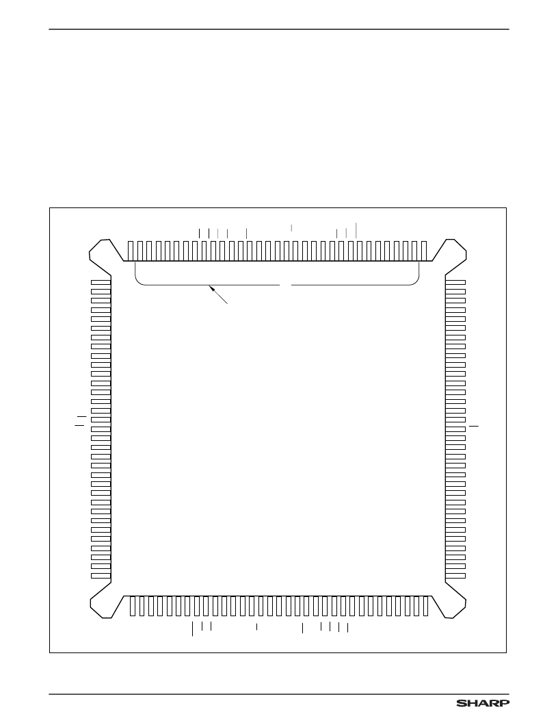
Figure 1. Pin Connections for 132-Pin PQFP Package
(Top View)
PIN CONNECTIONS
LH543601
256
×
36
×
2 Bidirectional FIFO
2
相關(guān)PDF資料 |
PDF描述 |
|---|---|
| LH543601M-20 | 256 x 36 x 2 Bidirectional FIFO |
| LH543601M-25 | 256 x 36 x 2 Bidirectional FIFO |
| LH543601M-30 | 256 x 36 x 2 Bidirectional FIFO |
| LH543601M-35 | 256 x 36 x 2 Bidirectional FIFO |
| LH543601P-20 | 256 x 36 x 2 Bidirectional FIFO |
相關(guān)代理商/技術(shù)參數(shù) |
參數(shù)描述 |
|---|---|
| LH543601M-20 | 制造商:SHARP 制造商全稱:Sharp Electrionic Components 功能描述:256 x 36 x 2 Bidirectional FIFO |
| LH543601M-25 | 制造商:SHARP 制造商全稱:Sharp Electrionic Components 功能描述:256 x 36 x 2 Bidirectional FIFO |
| LH543601M-30 | 制造商:SHARP 制造商全稱:Sharp Electrionic Components 功能描述:256 x 36 x 2 Bidirectional FIFO |
| LH543601M-35 | 制造商:SHARP 制造商全稱:Sharp Electrionic Components 功能描述:256 x 36 x 2 Bidirectional FIFO |
| LH543601P-20 | 制造商:SHARP 制造商全稱:Sharp Electrionic Components 功能描述:256 x 36 x 2 Bidirectional FIFO |
發(fā)布緊急采購,3分鐘左右您將得到回復(fù)。